SNES:SNES Jr Pre-Assembled THS7374 Amp: Difference between revisions
No edit summary |
No edit summary |
||
| (4 intermediate revisions by the same user not shown) | |||
| Line 1: | Line 1: | ||
[[ | [[File:SNESVoultarAmp.jpg|thumb]] | ||
This page shows how to use a pre-assembled RGB Amp to bypass the SNES Mini's internal encoder and enable RGB (and depending on the board) and S-Video. The amp you purchase may not look exactly like the one pictured, however the installation will be the same for all unless otherwise noted. | |||
== Required Materials == | |||
* A pre-assembled amp board, such as one from [http://voultar.com/index.php?route=product/product&path=59&product_id=51&tracking=5824d766cf098 Voultar], [https://8bitmods.com/snes-rgb-amp-with-csync/ 8BitMods (Borti's board)], or [https://store.retrofixes.com/products/snes-jr-n64-rgb-upgrade-kit RetroFixes] | |||
* The 4.5mm tool that opens the SNES | |||
* Philips head screwdriver | |||
* Soldering iron, solder, and flux | |||
* 26-30 AWG wire | |||
* Heatshrink tubing (not required, but recommended) | |||
[[File: | == Installation == | ||
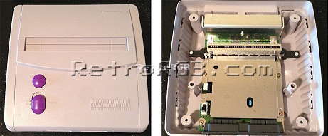
# Disassemble the console and remove the motherboard: <br> [[File:SNESMiniRGBPage00.jpg]] | |||
# Some SNES Mini's come from the factory with the two ground pins soldered together. If your system has this, you could either cut the solder in the middle (be really careful not to damage the pins), or use a solder-removing method (de-soldering iron, solder wick, etc) to remove it. Also, you'll most likely see some capacitor ends sticking out and interfering with the area you'll be mounting the board in. Just snip all four. <br> [[File:SNESMiniMultiOutInterference.jpg]] [[File:SNES_Multi-out_Component_Interference.jpg]] | |||
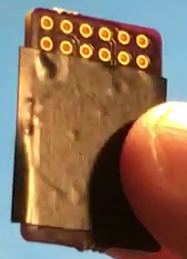
# Prepare the pre-made amp board. The bottom of the amp board has no components on it, however it's best to add a piece of non-conductive tape to the bottom to be safe. <br> [[File:SNES7374AmpTape.jpg]] | |||
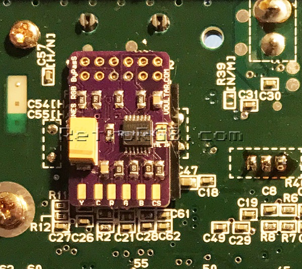
# Slide the amp over all the multi-out pins. Then carefully solder each pin, making sure not to let the solder spill over onto another pin. Flux helps, but isn't required. Add solder to all six pads on the bottom (the picture shown is pre-solder). <br> [[File:SNESVoultarAmpOnMultiOut.jpg]] | |||
# Locate the following spot on the motherboard: <br> [[File:SNESMiniRGBPage06.jpg]] | |||
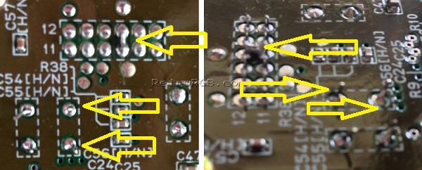
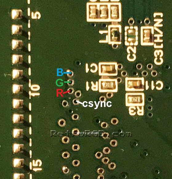
# Solder wire to the following via holes to get RGBs. It's recommended using flux on these vias. Make sure the stripped wire isn't too long, as it will stick out the top of the motherboard. <br> [[File:SNESMiniRGBsVIAs.jpg]] | |||
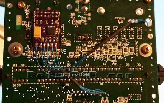
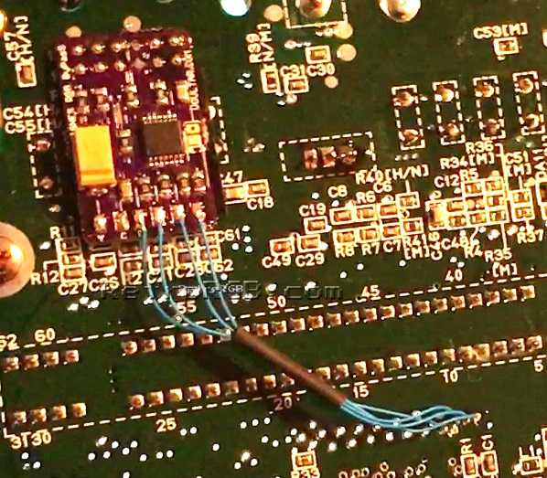
# Cut the wires to length and solder them to the corresponding RGBs pads on the amp, and add a bit of heat shrink tubing. Your installation should now look like this: <br> [[File:SNESVoultarAmpRGBInstall.jpg]] | |||
If your board only supports RGB, or if you don't plan on using S-Video, that's it! Otherwise, see the S-Video Installation instructions below. | |||
=== TTL Sync Jumper === | |||
[ | If you purchased the version 1 of Voultar's board or the RetroFixes board, you'll notice a jumper labeled "TTL" on it. That jumper will set the sync type. You will need to solder the jumper if you have a cable that attenuates TTL CSYNC to 75 ohm. | ||
* You can test if your cable attenuates TTL CSYNC to 75 ohm by use a multimeter in "continuity check" mode and probe pin 3 on the multi-out and the CSYNC pin on your cable head (pin 20 for SCART). If you get a beep indicating continuity, you do not need to bridge the jumper. If you get any value but no beep, bridge the jumper. | |||
*:[[File:SNESVoultarAmpTTLJumper.jpg]] | |||
* If you purchased the version 2 of Voultar's board, the TTL jumper is not present. The board is designed to work with both attenuated and unattenuated cables, but in the event that you have issues that require you to force TTL sync, removing this resistor will force TTL sync: | |||
*: [[File:Voultar SNESRGB TTL Resistor.png|200px]] | |||
=== LPF Jumper === | |||
The THS7374 chip also includes an additional low-pass filter to filter out noise, which can be toggled off and on. It's recommended for this filter be turned off (tie [https://www.ti.com/lit/ds/symlink/ths7374.pdf pin 9 to 5V]). Also, please keep in mind that this chip is MUCH smaller and almost impossible to solder by hand. As a result, it's not a good DIY solution, but great for surface-mount boards: | |||
:[[File:THS7374 Filter.png|500px]] | |||
=== S-Video Installation === | === S-Video Installation === | ||
If your amp board supports S-Video as well, you'll need to solder two more wires to the board. | If your amp board supports S-Video as well, you'll need to solder two more wires to the board. | ||
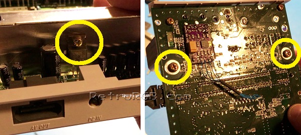
#Start by removing the screw that attaches the voltage regulator to the heatsink, then remove the two screws on the bottom of the motherboard that are holding the heatsink in place. [[File:SNESMiniHeatsinkScrews.jpg]] | # Start by removing the screw that attaches the voltage regulator to the heatsink, then remove the two screws on the bottom of the motherboard that are holding the heatsink in place. <br> [[File:SNESMiniHeatsinkScrews.jpg]] | ||
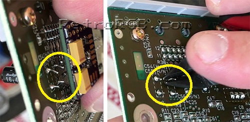
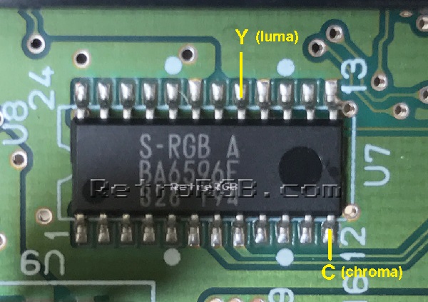
# | # Find the S-RGB chip that's right next to the cartridge port and solder one wire to luma (Y) and another to chroma (C) <br> [[File:SNESs-rgbY-C.jpg]] | ||
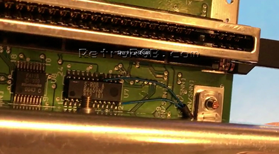
# | # Add a small amount of heatshrink tubing to the wires if you have it, then bolt the heatsink on over it. The wires will make contact with the heatsink but not be pinched. There is space between the heatsink and motherboard and the two wires fit nicely underneath. <br> [[File:SNESs-rgbYCwiresrun.jpg]] | ||
# | # Run the wires through the hole in the bottom of the motherboard (as shown on the right below) and solder them to the board: <br> [[File:SNESMiniTHS7374FullInstallation.jpg]] | ||
Latest revision as of 20:11, 31 July 2022

This page shows how to use a pre-assembled RGB Amp to bypass the SNES Mini's internal encoder and enable RGB (and depending on the board) and S-Video. The amp you purchase may not look exactly like the one pictured, however the installation will be the same for all unless otherwise noted.
Required Materials
- A pre-assembled amp board, such as one from Voultar, 8BitMods (Borti's board), or RetroFixes
- The 4.5mm tool that opens the SNES
- Philips head screwdriver
- Soldering iron, solder, and flux
- 26-30 AWG wire
- Heatshrink tubing (not required, but recommended)
Installation
- Disassemble the console and remove the motherboard:
- Some SNES Mini's come from the factory with the two ground pins soldered together. If your system has this, you could either cut the solder in the middle (be really careful not to damage the pins), or use a solder-removing method (de-soldering iron, solder wick, etc) to remove it. Also, you'll most likely see some capacitor ends sticking out and interfering with the area you'll be mounting the board in. Just snip all four.
- Prepare the pre-made amp board. The bottom of the amp board has no components on it, however it's best to add a piece of non-conductive tape to the bottom to be safe.
- Slide the amp over all the multi-out pins. Then carefully solder each pin, making sure not to let the solder spill over onto another pin. Flux helps, but isn't required. Add solder to all six pads on the bottom (the picture shown is pre-solder).
- Locate the following spot on the motherboard:
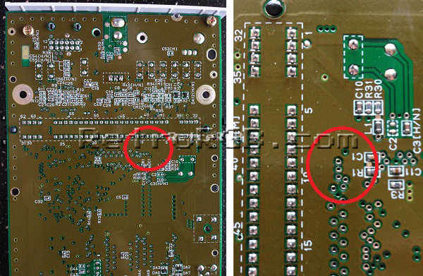
- Solder wire to the following via holes to get RGBs. It's recommended using flux on these vias. Make sure the stripped wire isn't too long, as it will stick out the top of the motherboard.
- Cut the wires to length and solder them to the corresponding RGBs pads on the amp, and add a bit of heat shrink tubing. Your installation should now look like this:


If your board only supports RGB, or if you don't plan on using S-Video, that's it! Otherwise, see the S-Video Installation instructions below.
TTL Sync Jumper
If you purchased the version 1 of Voultar's board or the RetroFixes board, you'll notice a jumper labeled "TTL" on it. That jumper will set the sync type. You will need to solder the jumper if you have a cable that attenuates TTL CSYNC to 75 ohm.
- You can test if your cable attenuates TTL CSYNC to 75 ohm by use a multimeter in "continuity check" mode and probe pin 3 on the multi-out and the CSYNC pin on your cable head (pin 20 for SCART). If you get a beep indicating continuity, you do not need to bridge the jumper. If you get any value but no beep, bridge the jumper.
- If you purchased the version 2 of Voultar's board, the TTL jumper is not present. The board is designed to work with both attenuated and unattenuated cables, but in the event that you have issues that require you to force TTL sync, removing this resistor will force TTL sync:


LPF Jumper
The THS7374 chip also includes an additional low-pass filter to filter out noise, which can be toggled off and on. It's recommended for this filter be turned off (tie pin 9 to 5V). Also, please keep in mind that this chip is MUCH smaller and almost impossible to solder by hand. As a result, it's not a good DIY solution, but great for surface-mount boards:

S-Video Installation
If your amp board supports S-Video as well, you'll need to solder two more wires to the board.
- Start by removing the screw that attaches the voltage regulator to the heatsink, then remove the two screws on the bottom of the motherboard that are holding the heatsink in place.
- Find the S-RGB chip that's right next to the cartridge port and solder one wire to luma (Y) and another to chroma (C)
- Add a small amount of heatshrink tubing to the wires if you have it, then bolt the heatsink on over it. The wires will make contact with the heatsink but not be pinched. There is space between the heatsink and motherboard and the two wires fit nicely underneath.
- Run the wires through the hole in the bottom of the motherboard (as shown on the right below) and solder them to the board: