SNES:SNES Jr S-Video Mod: Difference between revisions
Jump to navigation
Jump to search
No edit summary |
m (Derf moved page SNES:SNES Jr S-Video Mod to SNES:SNES Jr S-Video Mod) |
||
| (3 intermediate revisions by the same user not shown) | |||
| Line 1: | Line 1: | ||
[[File:SNESS-Video01.jpg|thumb]] | |||
[[File:SNESS-Video01.jpg]] | This page shows how to add S-Video output to a SNES Mini / Jr. system. Its strongly suggested that if you're going to mod your SNES Mini / Super Famicom Jr anyway, you'd might as well enable both RGB and S-Video at the same time. Often times S-Video is also available from pre-assembled boards. | ||
== Required Materials == | |||
* The 4.5mm tool that opens the SNES | |||
* Philips head screwdriver | |||
* Soldering iron and solder | |||
* 26-30 AWG wire | |||
* Heatshrink tubing | |||
* Two 75 Ohm resistors, the lowest tolerance possible: [http://www.digikey.com/product-detail/en/MRS25000C7509FRP00/PPC75.0ZCT-ND/595092] | |||
* One 0.1uf capacitor: [http://www.digikey.com/product-detail/en/C320C104J5R5TA7301/399-9867-1-ND/3726105] | |||
* One 220uf Capacitor: [http://www.digikey.com/product-detail/en/RR71A221MDN1/493-3712-ND/2207248] | |||
== Installation == | |||
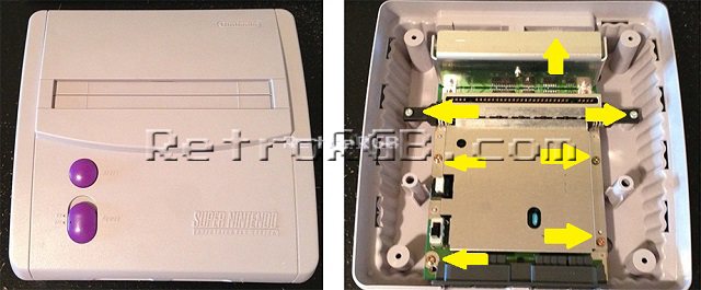
# Disassemble the console. <br> [[File:SNESMiniRGB-02.jpg]] | |||
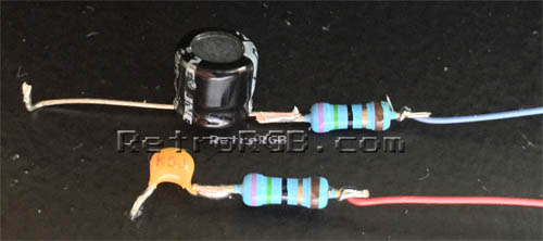
# Trim the negative end of the 220uf capacitor (usually the side marked with the stripe) and also trim an end of one the resistors to the same length. Add solder to each end, then solder them together. Do the same with the 0.1uf capacitor, but it doesn't matter which end you use. If both components are properly tinned, it should be an extremely tight connection and they will not come apart. Then add wires and heat shrink tubing to the resistor side. The heat shrink tubing is important, as it will prevent the components from shorting out against any exposed metal. <br> [[File:SNESS-Video04.jpg]] | |||
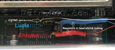
# Trim and bend the other ends of the capacitors as shown, then add solder to each end of the capacitor and each of the S-RGB pins shown in the picture below. The 220uf capacitor connects to luma and the 0.1uf capacitor connects to chroma. Make SURE the chroma capacitor is bent over the chip, or it will touch the heat shield when it is re-connected. <br> [[File:SNESS-Video02.jpg|400px]] | |||
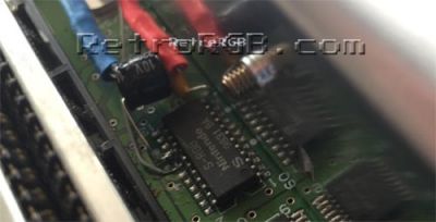
# Replace the heat shield and carefully run the cables around it, making sure the cables aren't pinched and nothing is touching the heat shield: <br> [[File:SNESS-Video01.jpg|400px]] | |||
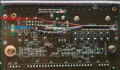
# Run the cables through the hole shown in the picture below, then trim the cables to their proper length. Add some heat shrink tubing to keep them together. Make sure that the wires are away from the mounting hole, then solder them to the pins on the multi-out shown below. The white wire in the picture is CSYNC, which is not needed for this mod, but used in a RGB mod. <br> [[File:SNESS-Video03.jpg|400px]] | |||
That's it! This will enable excellent quality S-Video output from your SNES Mini. It's not as good as RGB, but may be a good choice for your setup. | |||
That's it! | |||
Latest revision as of 15:16, 31 July 2022

This page shows how to add S-Video output to a SNES Mini / Jr. system. Its strongly suggested that if you're going to mod your SNES Mini / Super Famicom Jr anyway, you'd might as well enable both RGB and S-Video at the same time. Often times S-Video is also available from pre-assembled boards.
Required Materials
- The 4.5mm tool that opens the SNES
- Philips head screwdriver
- Soldering iron and solder
- 26-30 AWG wire
- Heatshrink tubing
- Two 75 Ohm resistors, the lowest tolerance possible: [1]
- One 0.1uf capacitor: [2]
- One 220uf Capacitor: [3]
Installation
- Disassemble the console.
- Trim the negative end of the 220uf capacitor (usually the side marked with the stripe) and also trim an end of one the resistors to the same length. Add solder to each end, then solder them together. Do the same with the 0.1uf capacitor, but it doesn't matter which end you use. If both components are properly tinned, it should be an extremely tight connection and they will not come apart. Then add wires and heat shrink tubing to the resistor side. The heat shrink tubing is important, as it will prevent the components from shorting out against any exposed metal.
- Trim and bend the other ends of the capacitors as shown, then add solder to each end of the capacitor and each of the S-RGB pins shown in the picture below. The 220uf capacitor connects to luma and the 0.1uf capacitor connects to chroma. Make SURE the chroma capacitor is bent over the chip, or it will touch the heat shield when it is re-connected.
- Replace the heat shield and carefully run the cables around it, making sure the cables aren't pinched and nothing is touching the heat shield:
- Run the cables through the hole shown in the picture below, then trim the cables to their proper length. Add some heat shrink tubing to keep them together. Make sure that the wires are away from the mounting hole, then solder them to the pins on the multi-out shown below. The white wire in the picture is CSYNC, which is not needed for this mod, but used in a RGB mod.


That's it! This will enable excellent quality S-Video output from your SNES Mini. It's not as good as RGB, but may be a good choice for your setup.