Saturn:FRAM Mod: Difference between revisions
Stuckaduck (talk | contribs) (Adding tutorial for FRAM mod for Sega Saturn) |
|||
| (10 intermediate revisions by 3 users not shown) | |||
| Line 1: | Line 1: | ||
{{Warning | This is an advanced mod. If care is not taken while removing the original memory chip, multiple solder pads can be lifted, which will result in an extremely difficult repair being necessary. The key to avoiding this is patience.}} | {{Warning | This is an advanced mod. If care is not taken while removing the original memory chip, multiple solder pads can be lifted, which will result in an extremely difficult repair being necessary. The key to avoiding this is patience.}} | ||
The system memory in the Sega Saturn is held in a volatile SRAM memory chip, which is powered by a CR2032 battery. This battery is also responsible for powering the real-time clock, which unfortunately drains the battery quite quickly. When the battery runs out, this results in all of the system's save data being lost. | The system memory in the Sega Saturn is held in a volatile SRAM memory chip, which is powered by a CR2032 battery. This battery is also responsible for powering the real-time clock, which unfortunately drains the battery quite quickly. When the battery runs out, this results in all of the system's save data being lost. | ||
This can be avoided by installing a non-volatile memory chip in place of the SRAM memory chip on the motherboard. FRAM memory is | This can be avoided by installing a non-volatile memory chip in place of the SRAM memory chip on the motherboard. FRAM memory is non-volatile memory that can be a direct replacement for SRAM and other volatile memory chips. The battery in the Saturn will typically only last for month, but with an FRAM chip, the system memory should be safe for decades at room temperature.<ref>https://en.wikipedia.org/wiki/Ferroelectric_RAM</ref> | ||
== Information == | == Information == | ||
This mod will work with all Saturn motherboard models, but note that the location and original SRAM chip model will differ based on motherboard revision. The original chip should be either UPD43257B or UM62257M. | This mod will work with all Saturn motherboard models, but note that the location and original SRAM chip model will differ based on motherboard revision. The original chip should be either UPD43257B or UM62257M. | ||
On many motherboards, the SRAM chip will be fixed to the board with adhesive in addition to solder on all legs. The main difficulty of this mod is in removing the original chip from the board. As mentioned above, patience is required for this mod. A very good example of the proper procedure for how to remove the original chip can be seen [https://www.youtube.com/watch?v=yfFM5lTEOMs&t=430s here, performed by Voultar]. He's removing a BIOS chip, but the process is exactly the same here. | On many motherboards, the SRAM chip will be fixed to the board with adhesive in addition to solder on all legs, due to being mounted upside down. The main difficulty of this mod is in removing the original chip from the board. As mentioned above, patience is required for this mod. A very good example of the proper procedure for how to remove the original chip can be seen [https://www.youtube.com/watch?v=yfFM5lTEOMs&t=430s here, performed by Voultar]. He's removing a BIOS chip, but the process is exactly the same here. | ||
The FM1808 chip is an almost direct analog to the original SRAM | The Cypress/Ramtron FM1808 chip is an almost direct analog to the original SRAM chip used on the Saturn. One small difference is that pin 22 on the old chip has a active-high CE signal, whereas the FM1808 has a active-low signal.<ref>https://www.retrorgb.com/sega-saturn-internal-memory-mod-with-fram-no-battery-required.html</ref> To account for this, pin 22 can be lifted and wired directly to ground. Additionally, the power for the old chip is wired to come from the save battery, so that the chip is constantly powered. Since that is not necessary for FRAM, this mod will wire it to 5V from elsewhere on the board. You should continue to use a clock battery for the system to remember the time. | ||
== Required Materials == | == Required Materials == | ||
| Line 18: | Line 17: | ||
** Multimeter with continuity mode | ** Multimeter with continuity mode | ||
** Tweezers | ** Tweezers | ||
** Philips head screwdriver | ** Philips head/JIS screwdriver | ||
* Components | * Components | ||
** FM1808 chip (FRAM memory module) | ** FM1808 chip (FRAM memory module) | ||
** Insulated wire | ** Insulated wire (preferably magnet wire) | ||
** | ** Leaded solder | ||
** Flux | ** Flux | ||
** Desoldering braid | ** Desoldering braid | ||
** Isopropyl alcohol (at least 90%) | ** Isopropyl alcohol (at least 90%) | ||
** Swabs for cleaning (microfiber/foam are better than cotton since they don't leave strands behind) | ** Swabs for cleaning (microfiber/foam are better than cotton since they don't leave strands behind) | ||
| Line 31: | Line 29: | ||
== Installation == | == Installation == | ||
=== | === Removing SRAM Chip === | ||
# Disassemble the console and pull out the motherboard | # Disassemble the console and pull out the motherboard. | ||
# Locate the SRAM chip | # Locate the SRAM chip. It should be marked with one of the following markings. Depending on the motherboard revision, the chip may be on the top or bottom of the motherboard. See Figure A1 for an example of what this looks like. | ||
#* UPD43257B | |||
#* UM62257AM | |||
#* UM62257M | |||
# Very carefully inspect the underside of the chip to see if there is adhesive underneath it. | #* SRM20257LL10 | ||
# Very carefully inspect the underside of the chip to see if there is adhesive underneath it. It might be hard to see at first glance if you aren't specifically looking for it. Lift up the motherboard a bit to the side to help see underneath it while looking for it. The adhesive will either be one large dot, or multiple very small dots of a dark colored material. If there is adhesive, be extra careful and allow much more time while using the hot air rework station than normal. | |||
#* VA-SG motherboards will typically have epoxy underneath the SRAM. Please see Figure B1 for an example of the epoxy. | |||
# Optionally, cover nearby components with kapton tape or foil to protect them from heat. | |||
# Turn on the hot air rework station and set it to 360 degrees Celsius with medium air flow. | |||
# | # Start by preheating the chip from a distance of 4-5 inches with the hot air station and very evenly distribute the heat around the chip for 30 seconds or so. | ||
# Turn on the hot air rework station and set it to 360 degrees Celsius with medium air flow | # Next, circle the perimeter of the chip with your hot air nozzle, making sure not to apply heat to any one location for too long. | ||
# Start by preheating the chip from a distance of 4-5 inches with the hot air station and very evenly distribute the heat around the chip for 30 seconds or so | #* Have patience. This will take time, especially if the chip has adhesive underneath it. The hot air at this temperature should not hurt the board as long as it is evenly applied. | ||
# Next, circle the perimeter of the chip with your hot air nozzle, making sure not to apply heat to any one location for too long | # While continuing the previous step, check if the chip has loosened with tweezers or another small implement by grabbing the side of the chip and gently try to lift without applying force. Once the chip is ready, it will easily come off. | ||
# | #* '''Warning''': If force is applied here, the solder and pads may pull up along with the chip! | ||
# Once the chip eventually separates from the board, turn off the hot air rework station. | |||
# While continuing the previous step, check if the chip has loosened with tweezers or another small implement | # Turn on the soldering iron and wick up any remaining solder on the pads with solder wick to make an even surface. Applying flux will make this process easier as it will help the old solder flow easier. | ||
# | |||
# Once the chip eventually | |||
# Turn on the soldering iron | |||
<gallery> | <gallery> | ||
Saturn original SRAM chip.png|Figure A1. Example SRAM chip | Saturn original SRAM chip.png|Figure A1. Example of an SRAM chip on a VA3 motherboard. | ||
Saturn SRAM chip adhesive.png|Figure B1. Example of adhesive under SRAM chip. | Saturn SRAM chip adhesive.png|Figure B1. Example of the adhesive under the SRAM chip. | ||
</gallery> | </gallery> | ||
=== | === Installing FRAM Chip === | ||
# Lift pins 22 and 28 on the FM1808 chip | # Lift pins 22 and 28 on the FM1808 chip. Figure A2 shows a pinout of the chip which shows which pins these are. | ||
# | #* See the explanation in the Information section on why this is necessary. | ||
# | #* Alternatively, the traces for the pads going to pins 22 and 28 can be cut for a cleaner install. If doing so, be *extremely* careful to only cut the traces for these pads. | ||
# Place the chip on the board, | # Place the chip on the board, making sure the orientation of the chip matches the marking on the board. | ||
# Line up the legs with pads | # Line up the legs with the pads, and apply some flux to one corner. | ||
# Once satisfied, tack one leg down with the soldering iron to fix the chip in place | # Once satisfied with the alignment, tack one leg down with the soldering iron to fix the chip in place. | ||
# Repeat on the other side of the chip to anchor the chip | #* It may help to gently rest a finger on top of the chip to hold it in place while you tack the first leg down. | ||
# | # Repeat on the other side of the chip to anchor the chip. | ||
# | # Once the chip is aligned, apply a generous amount of flux, and then solder the rest of the legs down with a dragging technique. | ||
# Use the multimeter to double check that no legs are bridged, and that all legs have good connections to the board | #* Ensure that all legs aside from 22 and 28 are soldered to the pads on the board with good solder joints. | ||
# Identify nearby solder points to get ground and 5V | # Use the multimeter to double check that no legs are bridged with their neighboring pins, and that all legs have good connections to the board. | ||
# Identify nearby solder points to get ground and 5V. Most Saturn motherboards should either have a neighboring chip or unpopulated pad that has 5V available. Depending on the location of the chip, a good ground point might be on one of the various exposed points on the edge of the board. | |||
#* See Figure B2 for an example of solder points specifically for the VA3 motherboard. | |||
# | #* For any other board, use a multimeter in continuity mode to identify a 5V point. The power supply connector in the corner of the motherboard is a great place to start with testing for this. See figure C2 for an identification of the 5V pin on the top of the motherboard, and D2 for the bottom. | ||
# | #** Touch one probe of the multimeter to the 5V pin on the connector, and then use the other probe to test other nearby solder points until the multimeter produces a long tone. This could be a leg on a chip, capacitor, test pad, etc. | ||
# Cut two lengths of wire, one sized to go between pin 28 and 5V, and the other to go between pin 22 and ground. | |||
# Tin the ends of the wires and solder points. | |||
# | # Solder the wires to their respective solder points and pins. | ||
# Use a multimeter to ensure a good connection between the conductors. | |||
# Cut two lengths of wire, one sized to go between pin 28 and 5V, and the other to go between pin 22 and ground | # Verify that 5V and ground are '''not''' shorted together. | ||
# Tin the ends of the wires and solder points | # Clean up any excess flux with some isopropyl alcohol and swabs. | ||
# Solder the wires to their respective solder points and pins | # Reassemble the Saturn but leave the top case unscrewed so that it is easier to disassemble. Alternatively, the top case can be left out but the disc door pinswitch will need to be held closed, since you will need to test with a game. | ||
# Use a multimeter to ensure | # Power on the console, and save some data to the system memory. | ||
# Verify that 5V and ground are '''not''' shorted together | # Power off the console and disconnect the power for at least 30 seconds. | ||
# | # Power it back on and verify that the memory is still saved. If so, the installation is complete. | ||
# | |||
# Power on the console, and save some data to the system memory | |||
# Power off the console and disconnect the power for at least 30 seconds | |||
# Power it back on and verify that the memory is still saved. If so, the installation is complete. | |||
<gallery> | <gallery> | ||
FM1808 pinout identifying lifted pins.png|Figure A2. FM1808 pinout with pins that need to be lifted identified. | FM1808 pinout identifying lifted pins.png|Figure A2. FM1808 pinout with the pins that need to be lifted identified. | ||
Saturn VA3 FRAM solder points.png|Figure B2. Example solder points on VA3 motherboard. | Saturn VA3 FRAM solder points.png|Figure B2. Example of 5V and ground solder points on a VA3 motherboard. | ||
Saturn 5V pin top.png|Figure C2. 5V pin on the top of the motherboard | Saturn 5V pin top.png|Figure C2. 5V pin on the top of the motherboard | ||
Saturn 5V pin bottom.png|Figure D2. 5V | Saturn 5V pin bottom.png|Figure D2. 5V pin on the bottom of the motherboard | ||
Saturn completed FRAM mod.jpg|Figure E2. Example completed FRAM mod on a VA3 motherboard | Saturn completed FRAM mod.jpg|Figure E2. Example of a completed FRAM mod on a VA3 motherboard | ||
saturnva4fram.jpg|Example of a completed FRAM mod on a VA4 motherboard. In this example, the traces for pins 22 and 28 were cut and the appropriate pins on the FRAM chip were rewired without being lifted for a cleaner install. | |||
</gallery> | </gallery> | ||
== Troubleshooting == | == Troubleshooting == | ||
If the installation does not go according to plan, here are some simple troubleshooting steps: | |||
* Double check that the wires are connected to ground and 5V respectively | * Double check that the wires on the lifted FRAM pins are connected to ground and 5V respectively. | ||
* Double check that no adjacent pins are shorted together | * Double check that no adjacent pins are shorted together. | ||
* Double check that all pins are connected to the solder pads | * Double check that all pins are connected to the solder pads. | ||
* Follow the trace of each leg of the chip and verify continuity if possible | * Follow the trace of each leg of the chip and verify continuity if possible. | ||
** Some traces might go to a via that's underneath another chip. It should be accessible on the other side of the board. | ** Some traces might go to a via that's underneath another chip. It should be accessible on the other side of the board. | ||
** If there isn't continuity, the solder pad might have been lifted, and a jumper wire may be necessary | ** If there isn't continuity, the solder pad might have been lifted, and a jumper wire may be necessary. | ||
* Verify that the lifted legs / conducting wires aren't shorting on the RF shielding of the case | * Verify that the lifted legs / conducting wires aren't shorting on the RF shielding of the case. | ||
== References == | == References == | ||
[[Category:Saturn]] | |||
Latest revision as of 20:43, 5 April 2024
| This is an advanced mod. If care is not taken while removing the original memory chip, multiple solder pads can be lifted, which will result in an extremely difficult repair being necessary. The key to avoiding this is patience. |
The system memory in the Sega Saturn is held in a volatile SRAM memory chip, which is powered by a CR2032 battery. This battery is also responsible for powering the real-time clock, which unfortunately drains the battery quite quickly. When the battery runs out, this results in all of the system's save data being lost.
This can be avoided by installing a non-volatile memory chip in place of the SRAM memory chip on the motherboard. FRAM memory is non-volatile memory that can be a direct replacement for SRAM and other volatile memory chips. The battery in the Saturn will typically only last for month, but with an FRAM chip, the system memory should be safe for decades at room temperature.[1]
Information
This mod will work with all Saturn motherboard models, but note that the location and original SRAM chip model will differ based on motherboard revision. The original chip should be either UPD43257B or UM62257M.
On many motherboards, the SRAM chip will be fixed to the board with adhesive in addition to solder on all legs, due to being mounted upside down. The main difficulty of this mod is in removing the original chip from the board. As mentioned above, patience is required for this mod. A very good example of the proper procedure for how to remove the original chip can be seen here, performed by Voultar. He's removing a BIOS chip, but the process is exactly the same here.
The Cypress/Ramtron FM1808 chip is an almost direct analog to the original SRAM chip used on the Saturn. One small difference is that pin 22 on the old chip has a active-high CE signal, whereas the FM1808 has a active-low signal.[2] To account for this, pin 22 can be lifted and wired directly to ground. Additionally, the power for the old chip is wired to come from the save battery, so that the chip is constantly powered. Since that is not necessary for FRAM, this mod will wire it to 5V from elsewhere on the board. You should continue to use a clock battery for the system to remember the time.
Required Materials
- Tools
- Soldering iron
- Hot air rework station
- Multimeter with continuity mode
- Tweezers
- Philips head/JIS screwdriver
- Components
- FM1808 chip (FRAM memory module)
- Insulated wire (preferably magnet wire)
- Leaded solder
- Flux
- Desoldering braid
- Isopropyl alcohol (at least 90%)
- Swabs for cleaning (microfiber/foam are better than cotton since they don't leave strands behind)
Installation
Removing SRAM Chip
- Disassemble the console and pull out the motherboard.
- Locate the SRAM chip. It should be marked with one of the following markings. Depending on the motherboard revision, the chip may be on the top or bottom of the motherboard. See Figure A1 for an example of what this looks like.
- UPD43257B
- UM62257AM
- UM62257M
- SRM20257LL10
- Very carefully inspect the underside of the chip to see if there is adhesive underneath it. It might be hard to see at first glance if you aren't specifically looking for it. Lift up the motherboard a bit to the side to help see underneath it while looking for it. The adhesive will either be one large dot, or multiple very small dots of a dark colored material. If there is adhesive, be extra careful and allow much more time while using the hot air rework station than normal.
- VA-SG motherboards will typically have epoxy underneath the SRAM. Please see Figure B1 for an example of the epoxy.
- Optionally, cover nearby components with kapton tape or foil to protect them from heat.
- Turn on the hot air rework station and set it to 360 degrees Celsius with medium air flow.
- Start by preheating the chip from a distance of 4-5 inches with the hot air station and very evenly distribute the heat around the chip for 30 seconds or so.
- Next, circle the perimeter of the chip with your hot air nozzle, making sure not to apply heat to any one location for too long.
- Have patience. This will take time, especially if the chip has adhesive underneath it. The hot air at this temperature should not hurt the board as long as it is evenly applied.
- While continuing the previous step, check if the chip has loosened with tweezers or another small implement by grabbing the side of the chip and gently try to lift without applying force. Once the chip is ready, it will easily come off.
- Warning: If force is applied here, the solder and pads may pull up along with the chip!
- Once the chip eventually separates from the board, turn off the hot air rework station.
- Turn on the soldering iron and wick up any remaining solder on the pads with solder wick to make an even surface. Applying flux will make this process easier as it will help the old solder flow easier.
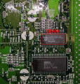
Figure A1. Example of an SRAM chip on a VA3 motherboard.
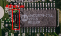
Figure B1. Example of the adhesive under the SRAM chip.


Installing FRAM Chip
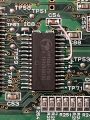
- Lift pins 22 and 28 on the FM1808 chip. Figure A2 shows a pinout of the chip which shows which pins these are.
- See the explanation in the Information section on why this is necessary.
- Alternatively, the traces for the pads going to pins 22 and 28 can be cut for a cleaner install. If doing so, be *extremely* careful to only cut the traces for these pads.
- Place the chip on the board, making sure the orientation of the chip matches the marking on the board.
- Line up the legs with the pads, and apply some flux to one corner.
- Once satisfied with the alignment, tack one leg down with the soldering iron to fix the chip in place.
- It may help to gently rest a finger on top of the chip to hold it in place while you tack the first leg down.
- Repeat on the other side of the chip to anchor the chip.
- Once the chip is aligned, apply a generous amount of flux, and then solder the rest of the legs down with a dragging technique.
- Ensure that all legs aside from 22 and 28 are soldered to the pads on the board with good solder joints.
- Use the multimeter to double check that no legs are bridged with their neighboring pins, and that all legs have good connections to the board.
- Identify nearby solder points to get ground and 5V. Most Saturn motherboards should either have a neighboring chip or unpopulated pad that has 5V available. Depending on the location of the chip, a good ground point might be on one of the various exposed points on the edge of the board.
- See Figure B2 for an example of solder points specifically for the VA3 motherboard.
- For any other board, use a multimeter in continuity mode to identify a 5V point. The power supply connector in the corner of the motherboard is a great place to start with testing for this. See figure C2 for an identification of the 5V pin on the top of the motherboard, and D2 for the bottom.
- Touch one probe of the multimeter to the 5V pin on the connector, and then use the other probe to test other nearby solder points until the multimeter produces a long tone. This could be a leg on a chip, capacitor, test pad, etc.
- Cut two lengths of wire, one sized to go between pin 28 and 5V, and the other to go between pin 22 and ground.
- Tin the ends of the wires and solder points.
- Solder the wires to their respective solder points and pins.
- Use a multimeter to ensure a good connection between the conductors.
- Verify that 5V and ground are not shorted together.
- Clean up any excess flux with some isopropyl alcohol and swabs.
- Reassemble the Saturn but leave the top case unscrewed so that it is easier to disassemble. Alternatively, the top case can be left out but the disc door pinswitch will need to be held closed, since you will need to test with a game.
- Power on the console, and save some data to the system memory.
- Power off the console and disconnect the power for at least 30 seconds.
- Power it back on and verify that the memory is still saved. If so, the installation is complete.
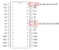
Figure A2. FM1808 pinout with the pins that need to be lifted identified.
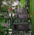
Figure B2. Example of 5V and ground solder points on a VA3 motherboard.
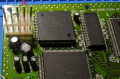
Figure C2. 5V pin on the top of the motherboard
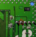
Figure D2. 5V pin on the bottom of the motherboard
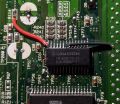
Figure E2. Example of a completed FRAM mod on a VA3 motherboard
Example of a completed FRAM mod on a VA4 motherboard. In this example, the traces for pins 22 and 28 were cut and the appropriate pins on the FRAM chip were rewired without being lifted for a cleaner install.


Troubleshooting
If the installation does not go according to plan, here are some simple troubleshooting steps:
- Double check that the wires on the lifted FRAM pins are connected to ground and 5V respectively.
- Double check that no adjacent pins are shorted together.
- Double check that all pins are connected to the solder pads.
- Follow the trace of each leg of the chip and verify continuity if possible.
- Some traces might go to a via that's underneath another chip. It should be accessible on the other side of the board.
- If there isn't continuity, the solder pad might have been lifted, and a jumper wire may be necessary.
- Verify that the lifted legs / conducting wires aren't shorting on the RF shielding of the case.