Xbox 360:JTAG/Boxxdr Method: Difference between revisions
Jump to navigation
Jump to search
mNo edit summary |
mNo edit summary |
||
| (4 intermediate revisions by 2 users not shown) | |||
| Line 1: | Line 1: | ||
This JTAG | [[Category:Xbox360]] | ||
This is the JTAG and R-JTOP wiring for Zephyr, Falcon/Opus, and Jasper motherboards. This method may disable 5.1 audio output. | |||
== Equipment Needed == | |||
==Equipment Needed== | * A soldering iron, solder, flux, isopropyl alcohol, and cotton swabs | ||
* A soldering iron, solder, | **[[Recommended Soldering Equipment|Specific recommendatons can be found on this page]] | ||
* 28AWG or 30AWG wire (Solid core recommended) | |||
* 28AWG or 30AWG wire | * Two 10K Ohm 1/2W or 1/4W resistors (Brown, Black, Red, Gold) | ||
* Two 10K Ohm 1/2W or 1/4W resistors | |||
* Two 2N3904 transistors | * Two 2N3904 transistors | ||
* | * Wire Insulation (kapton tape, electrical tape, heatshrink, etc.) | ||
==Motherboard Soldering== | ==Motherboard Soldering== | ||
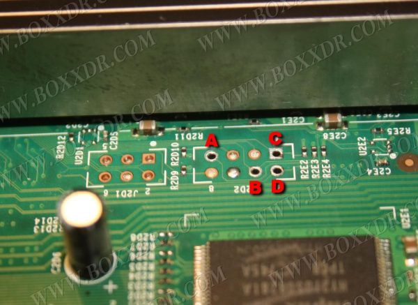
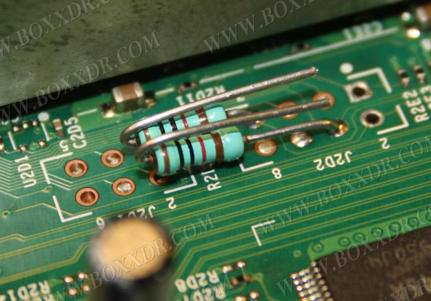
# Bend the legs of the two resistors to match the image below and solder them to points A and B by melting the existing solder and pushing the legs through. Ensure that there is enough of each leg underneath the board so that they can be soldered together. <br>[[File:Non-Xenon-JTAG1.png|600x600px]] [[File:Non-Xenon-JTAG2.png|625x625px]] | |||
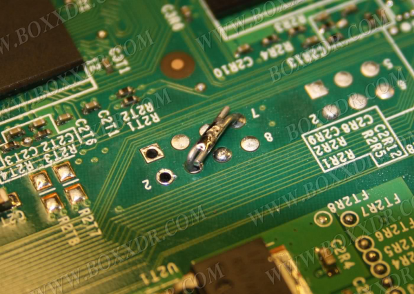
# Solder the legs together underneath the board, taking care to avoid them touching the other metal points on the board. <br> [[File:Non-Xenon-JTAG3.png|600x600px]] | |||
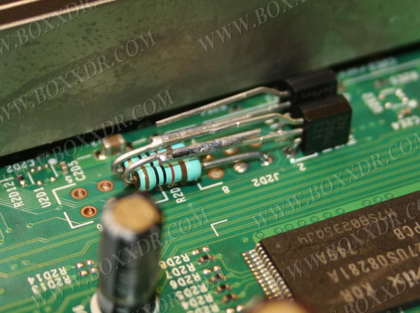
# Bend the legs of the two resistors to match the image below and solder them to points A and B by melting the existing solder and pushing the legs through. Ensure that there is enough of each leg underneath the board so that they can be soldered together. <br> [[File:Non-Xenon-JTAG2.png]] | # Bend the bottom leg of one the transistors as shown in the image below, making sure that the writing on the transistor faces away from the heatsink. Solder the bottom leg to point C by melting the existing solder and pushing the leg through. Solder the middle leg to the resistor attached to point A. Repeat this process for the other transistor and its respective resistor. <br> [[File:Non-Xenon-JTAG4.png|600x600px]] | ||
# Solder the legs together underneath the board, taking care to avoid them touching the other metal points on the board. <br> [[File:Non-Xenon-JTAG3.png]] | # Cut two long strands of wire, soldering one to each of the top legs of the transistors. Cut a piece of heat shrink tubing long enough to cover each of the top legs, then heat it using a hair dryer until it stops shrinking. This will prevent accidental shorting of the wires. <br> [[File:Non-Xenon-JTAG5.png|600x600px]] | ||
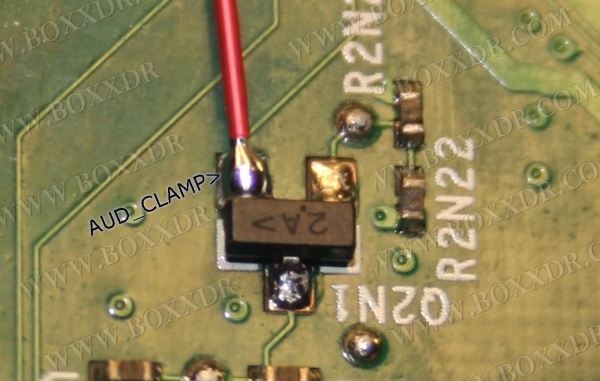
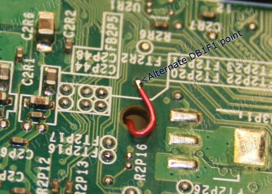
# Bend the bottom leg of one the transistors as shown in the image below, making sure that the writing on the transistor faces away from the heatsink. Solder the bottom leg to point C by melting the existing solder and pushing the leg through. Solder the middle leg to the resistor attached to point A. Repeat this process for the other transistor and its respective resistor. <br> [[File:Non-Xenon-JTAG4.png]] | # Feed the wires through the holes shown below, soldering them to the respective points on the underside of the board. Ensure that your wiring is correct and that the correct line is connected to each point. <br> [[File:Non-Xenon-JTAG6.png|600x600px]] [[File:Non-Xenon-JTAG7.png|534x534px]] | ||
# Cut two long strands of wire, soldering one to each of the top legs of the transistors. Cut a piece of heat shrink tubing long enough to cover each of the top legs, then heat it using a hair dryer until it stops shrinking. This will prevent accidental shorting of the wires. <br> [[File:Non-Xenon-JTAG5.png]] | |||
# Feed the wires through the holes shown below, soldering them to the respective points on the underside of the board. Ensure that your wiring is correct and that the correct line is connected to each point. <br> [[File:Non-Xenon-JTAG6.png]] | |||
==Testing your Console== | ==Testing your Console== | ||
Once you've finished soldering, clean up any flux with isopropyl alcohol and cotton swabs. Partially re-assemble your Xbox 360, ensuring that: | Once you've finished soldering, clean up any flux with isopropyl alcohol and cotton swabs. Partially re-assemble your Xbox 360, ensuring that: | ||
* Heatsinks are attached (if you removed them for some reason) | * Heatsinks are attached (if you removed them for some reason) | ||
* Fans are in place and plugged in | * Fans are in place and plugged in (You can angle the fans on top of the heatsinks to cool them for testing) | ||
* The Ring of Light board is plugged into the front of your console | * The Ring of Light board is plugged into the front of your console | ||
* Your | * Your A/V or HDMI cable is plugged into the Xbox 360 and into a TV or monitor | ||
* Your power brick is plugged in to both | * Your power brick is plugged in to both the wall and Xbox 360 | ||
* (Optional) An ethernet cable is plugged into the Xbox 360 and your LAN (e.g. a switch, router, or directly to a PC) | |||
Turn on your console, and it should boot into XeLL within a minute. If you don't have an ethernet cable connected, write down (and/or take a picture of) the "CPU Key" listed on screen. You can now go back to the [[Xbox 360:JTAG#Decrypting the NAND|'''JTAG''']] or [[Xbox 360:R-JTOP#Decrypting the NAND|'''R-JTOP''']] hack page and continue from the beginning of the "Decrypting The NAND" section. | |||
==Troubleshooting== | *If your console doesn't boot into XeLL, check all previous steps and double check your wiring accuracy and quality. If your soldering/wiring is perfect and it still doesn't boot, you receive E79 errors, or you have issues with HDMI; you may have a rare console that needs the '''[[Xbox 360:JTAG/Boxxdr Method + Open Tray|Boxxdr + Open_Tray]]''' method. | ||
* '''What should I do if I ripped off a soldering pad?''' | ==Troubleshooting== | ||
*'''What should I do if I ripped off a soldering pad?''' | |||
** Look online for an alternate point to solder onto. Practice more on junk electronics before attempting to continue. | ** Look online for an alternate point to solder onto. Practice more on junk electronics before attempting to continue. | ||
Latest revision as of 22:41, 7 September 2023
This is the JTAG and R-JTOP wiring for Zephyr, Falcon/Opus, and Jasper motherboards. This method may disable 5.1 audio output.
Equipment Needed
- A soldering iron, solder, flux, isopropyl alcohol, and cotton swabs
- 28AWG or 30AWG wire (Solid core recommended)
- Two 10K Ohm 1/2W or 1/4W resistors (Brown, Black, Red, Gold)
- Two 2N3904 transistors
- Wire Insulation (kapton tape, electrical tape, heatshrink, etc.)
Motherboard Soldering
- Bend the legs of the two resistors to match the image below and solder them to points A and B by melting the existing solder and pushing the legs through. Ensure that there is enough of each leg underneath the board so that they can be soldered together.
- Solder the legs together underneath the board, taking care to avoid them touching the other metal points on the board.
- Bend the bottom leg of one the transistors as shown in the image below, making sure that the writing on the transistor faces away from the heatsink. Solder the bottom leg to point C by melting the existing solder and pushing the leg through. Solder the middle leg to the resistor attached to point A. Repeat this process for the other transistor and its respective resistor.
- Cut two long strands of wire, soldering one to each of the top legs of the transistors. Cut a piece of heat shrink tubing long enough to cover each of the top legs, then heat it using a hair dryer until it stops shrinking. This will prevent accidental shorting of the wires.
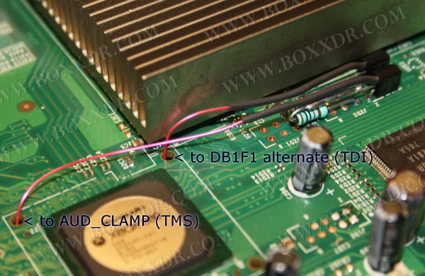
- Feed the wires through the holes shown below, soldering them to the respective points on the underside of the board. Ensure that your wiring is correct and that the correct line is connected to each point.


Testing your Console
Once you've finished soldering, clean up any flux with isopropyl alcohol and cotton swabs. Partially re-assemble your Xbox 360, ensuring that:
- Heatsinks are attached (if you removed them for some reason)
- Fans are in place and plugged in (You can angle the fans on top of the heatsinks to cool them for testing)
- The Ring of Light board is plugged into the front of your console
- Your A/V or HDMI cable is plugged into the Xbox 360 and into a TV or monitor
- Your power brick is plugged in to both the wall and Xbox 360
- (Optional) An ethernet cable is plugged into the Xbox 360 and your LAN (e.g. a switch, router, or directly to a PC)
Turn on your console, and it should boot into XeLL within a minute. If you don't have an ethernet cable connected, write down (and/or take a picture of) the "CPU Key" listed on screen. You can now go back to the JTAG or R-JTOP hack page and continue from the beginning of the "Decrypting The NAND" section.
- If your console doesn't boot into XeLL, check all previous steps and double check your wiring accuracy and quality. If your soldering/wiring is perfect and it still doesn't boot, you receive E79 errors, or you have issues with HDMI; you may have a rare console that needs the Boxxdr + Open_Tray method.
Troubleshooting
- What should I do if I ripped off a soldering pad?
- Look online for an alternate point to solder onto. Practice more on junk electronics before attempting to continue.