Xbox 360:RGH/RGH3
RGH 3 is a modern method of the Reset Glitch Hack that uses the SMC in the Xbox 360's southbridge instead of a glitch chip in order to boot unsigned code.
MrMario2011 has video guides for RGH 3 on Falcon/Jasper[1], Trinity[2], and Corona [3] motherboards respectively. The guides from Larvs on Xbox 360 Hub[4] and BeefyDJ on Se7enSins[5] are also great resources for RGH 3 tutorials.
| Phat consoles tend to be more stubborn with RGH3, and may have inconsistant booting behavior. It is recommended to use RGH 1.2 on a phat system, as it will be more stable. |
Equipment Needed
- A soldering iron, solder, flux, and Isopropyl alcohol with cotton swabs
- 28-30AWG Wire (Solid core recommended)
- An SMD or through hole resistor (Required on Phat)
- Falcon/Jasper: 22K Ohm (Red, Red, Orange, Yellow)
- Trinity: 3K-10K Ohm (10K resistor color values are Brown, Black, Red, Gold)
- Corona: 1K Ohm (Optional, Brown, Black, Red, Gold)
- 1N4148 diode (Only Falcon/Jasper, highly recommended)
- Wire Insulation (kapton tape, electrical tape, heatshrink, etc.) for through hole resistors/diodes
- A PC running Windows Vista or later
- J-Runner with Extras
- Any compatible NAND Programmer (Listed in the NAND backup page)
- NAND Backup with RGH3 XeLL written to the console
RGH3 Wiring & Diagrams

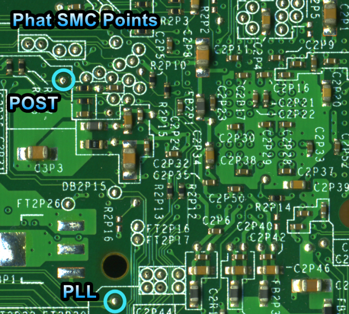
Phat (Falcon/Jasper)
On Falcon and Jasper motherboards, you can place the a diode on the wire that connects POST and SMC_POST. While it could be skipped, is not recommended to use RGH 3 on a Falcon or Jasper without this diode, as the boot times will be more unstable or inconstant without it. When using a through hole diode, it is recommended to solder it in the middle of the wire instead of soldering it directly to a pad. The wires will be less stiff than the diode's legs, causing less strain to the joint if it moves around. This also applies to the 22K resistor on the wire connecting PLL and SMC_PLL.
It is not recommended to use RGH 3 on Falcon or Jasper without the suggested resistor.
CPU Solder Points
CPU PLL
- Bottom
- Top


CPU POST
- Bottom
- Top


SMC Solder Points
- Alternative SMC_PLL (Top)
- Alternative SMC_PLL (Top)


Slim (Trinity)
On Trinity, it is recommended to use a 3K to 10K Ohm resistor on the PLL wire. The resistor on Trinity is optional, but recommended for reliability if available. The diode on the POST wire is not used on Trinity or Corona. When using a through hole resistor, it is recommended to solder it in the middle of the wire instead of soldering it directly to a pad. The wires will be less stiff than the diode's legs, causing less strain to the joint if it moves around.
CPU Solder Points
- CPU PLL (Bottom, no alt point!)
- CPU POST (Bottom, RST can be ignored with RGH3)


SMC Solder Points
- SMC_PLL
- SMC_POST


Slim or E (Corona/Waitsburg/Stingray)
The 1K Ohm resistor on Corona motherboards is optional, but still recommended for reliability if available. It also connects to the wire connecting SMC_PLL and the CPU's PLL. When using a through hole resistor, it is recommended to solder it in the middle of the wire instead of soldering it directly to a pad. The wires will be less stiff than the diode's legs, causing less strain to the joint if it moves around. Make sure to check if the POST point on the bottom is enabled or not using the provided diagram.
CPU Solder Points
- CPU PLL (Bottom, no alt point!)
- CPU POST (Bottom, RST can be ignored with RGH3)

SMC Solder Points
- Bottom

Decrypting the NAND
- Connect an Ethernet cable and HDMI cable to the console and power it on. The glitch chip should blink once or more times, and then the console should start into XeLL RELOADED.
- Once XeLL finishes, it will display your CPU key and some other info. There is also an IP address.
- Enter the IP address into the box on the lower right of J-Runner and click "Get CPU Key". J-Runner will pull the info from the box, and decrypt the NANDs automatically.
- If you don't want to or aren't able to connect the Xbox 360 to a network or directly to the PC, you can also manually type in the CPU key from XeLL into J-Runner.
Writing New NAND Image
- Power down the console, and connect your programmer to the motherboard.
- If you are using an xFlasher, ensure the switch is set to
SPI.
- If you are using an xFlasher, ensure the switch is set to
- In the upper right of J-Runner, ensure the
Glitch2radio button is selected. Since RGH3 XeLL was written to the NAND earlier, Glitch2 and RGH3 should already be enabled. - Click "Create XeBuild Image". This will take a few moments.
- Click "Write NAND".
- Disconnect your programmer when the process completes.
- Boot the console several times and ensure it boots consistently. If not, make sure your wiring is clean and neat and avoids noisy areas. Run the wires near the X-Clamps for best results.
- Return to the RGH main page and continue in the Cleaning Up section.