Innovation GBA TV Converter RGB Guide
(Redirected from Innovation GBA TV Converter RGB Guide)
Jump to navigation
Jump to search
This guide describes how to modify the Innovation GBA TV Converter to output RGB by rewiring the existing AV cable. Please keep in mind that this adapter only outputs interlaced 480i, not progressive 240p. If you've gone through the trouble of installing this adapter, the RGB mod is worth doing. Before you start this guide, make sure your Game Boy Advance is working properly both by itself and with the Innovation GBA TV Converter.
Required Materials
- Excellent soldering skills.
- Tri-wing screwdriver (the adapter comes with one, but it’s terrible)
- Philips head screwdriver.
- Soldering iron (with thin tip) / thin solder
- 26-30 AWG wire
- Three 75 ohm Resistors: DigiKey link
- A fourth 75 ohm resistor if using on a PAL TV
- Innovation GBA TV-out adapter
Installation
- First, disassemble the TV adapter and locate the video pins:
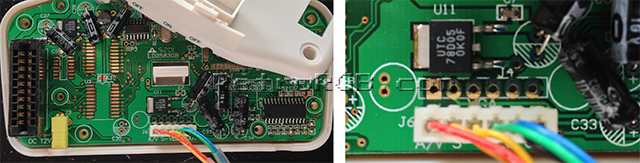
- Cut the wires from the existing wiring harness and solder them to the following pins (try to match the colors, as it will be easier on the other end of the cable). The
LandRaudio channels are optional, since you can just use the headphone jack on the GBA.
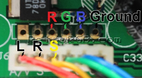
The syncSis actually the composite video out. There seems to be a Sony CXA chip (or clone) in this unit. You can get csync from the "sync-in" pin circled below. Please note that this is 5V TTL csync, so it may not be compatible with some SCART TVs expecting 1V p-p sync. You can probably pull RGB directly from the chip as well, but the solder points listed above are easier to solder to.
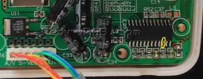
- Once you've soldered the video pins, you can decide if you'd like to pull audio directly from the board, or separately from the headphone-out of the GBA. Keep in mind that there are not enough wires inside of the stock cable to carry all of the required signals if you include a second audio signal so you would need to have one signal separate from the main cable. The connector that was on the board was removed here but its removal was unnecessary.
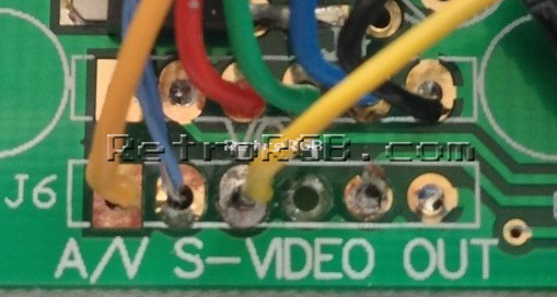
- This is one way to handle the extra signal wire — snaking it out of the notch in the cable and twisting it around the entire cable.
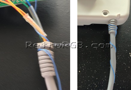
- This is one way to handle the extra signal wire — snaking it out of the notch in the cable and twisting it around the entire cable.
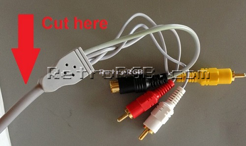
- Cut the other end of the cable at the connection point towards the end.


Wiring a SCART Connector

At this point, you need to solder the wires into a connector. Many people use SCART for RGB, but you can use anything you'd like, but ensure that you use the resistors as noted.
- Add 75 ohm resistors to each of the color wires. It's recommended to solder the resistors directly to the RGB pins; 15, 11, 7 and then solder the wires from the cable to the resistors.
- After that, follow the basic SCART diagram, wiring SYNC to pin 20 and L/R audio to pins 6 and 2 respectively. Ensure that all ground pins of the SCART connector are connected to each other (small white jumpers in picture below) and the ground wire from the cable is connected to one of them.
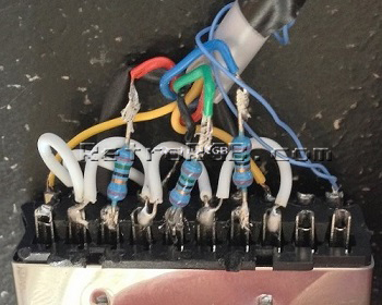
- For SCART, PAL TVs will require a 75 ohm resistor connecting pins 8 and 16. RGB monitors and upscalers shouldn't need this at all.
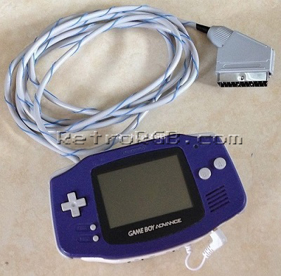
- Reassemble the SCART connector and test it. The finished product should look something like this:

