SNES Jr DIY Bypass
Jump to navigation
Jump to search

This mod shows you how to build your own THS7316 RGB amp to bypass the SNES Jr's internal amp. This isn't necessary and you can simply use the SNES Mini's built-in RGB encoder. This mod is just an alternative method. All pictures in this guide show the THS7314 amp, but it's recommended you use the THS7316 (installation is identical).
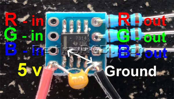
Comparison of the THS7314 and THS7316:

Required Materials
- The 4.5mm tool that opens the SNES
- Philips head screwdriver
- Soldering iron / solder
- 26-30 AWG wire
- RGB Amplifier chip, model # THS7316
- Circuit board to mount the RGB amp
- Three 75 Ohm resistors, the lowest tolerance possible
- Three 1.2k resistors, the lowest tolerance possible
Installation
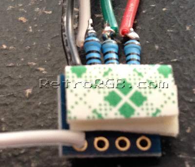
- Assemble the RGB amp circuit. After you cut the excess pins from the resistors, save them for later in this guide!
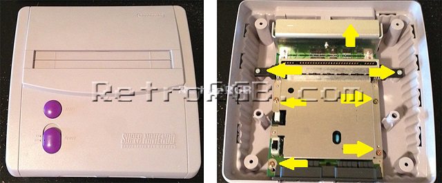
- Open the console by removing the 4 screws on the bottom of the case (using the 4mm SNES tool) and remove the 7 Philips screws from the board:
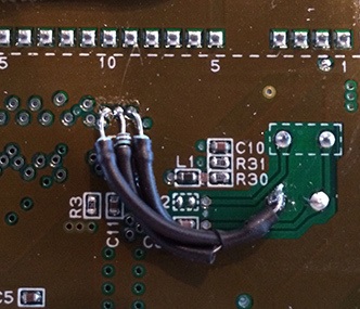
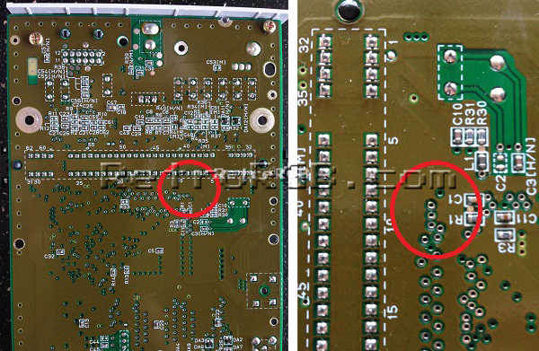
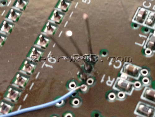
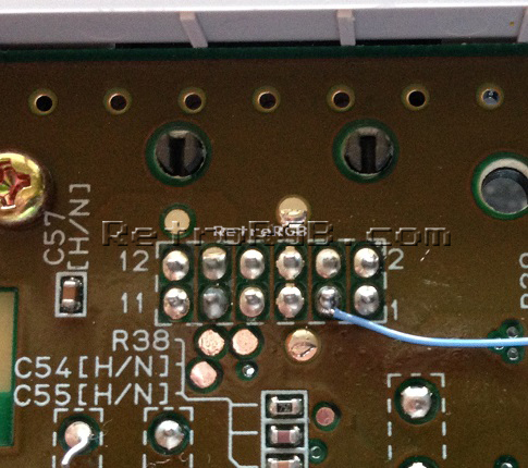
- Flip the board over and locate the following area:
- Take the excess pins left over from the resistors and add them to the RGB holes. You'll need to hold onto the pins with a pair of pliers or tweezers, as they'll get really hot. Then, use your soldering iron to heat up each one individually until they slide through the board and stick out a bit. Afterwards, heat them again, adding a bit of solder to each side to secure them in place. Finally, carefully snip off any excess that's sticking through the top (having some of the pin stick up is fine, as long as they aren't touching anything else). It should now look like this on the bottom of the board (please ignore the wire in this picture, it was from another mod):
- It's recommended to add two pieces of thick double-sided tape to the bottom of the RGB amp, as it makes a good cushion between the amp and the motherboard:
- Carefully slide the amp over the pins you just installed, solder them in place and cut any excess that's sticking out. Make sure to align RGB on the amp, with RGB on the board:
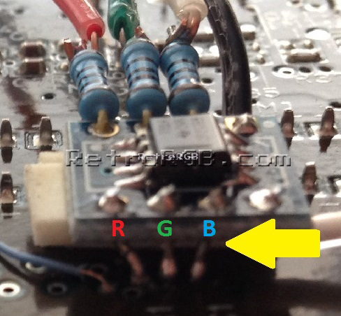
- Make sure the components on the RGB amp aren't touching anything on the motherboard (this is where the two pieces of thick double side tape come in handy):
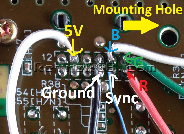
- Cut the wires down to size and solder them to the A/V port. There are other places on the board to find 5v and ground, however the A/V port is easiest in this case as the pins are big. When you run the wires, be aware of the mounting hole, as you won't want any of the wires to get pinched:
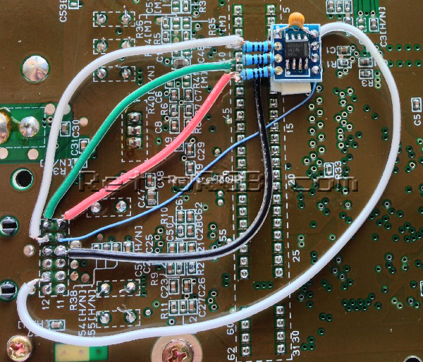
Your installation should look like this (ignore the blue wire). If you are planning on using sync-on-luma, you are done.
- If you wish to use CSYNC:
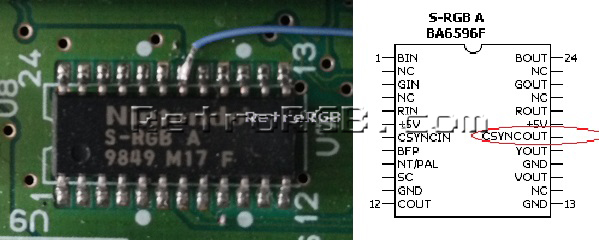
- Flip the motherboard over and solder a wire to pin 18 on the S-RGB chip:
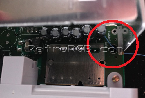
- Run that wire through the hole near the heatsink, but make sure when you replace the heatsink that it is not pinched:
- Trim any slack from the wire and solder the cable to pin 3 of the multi-out:
- Flip the motherboard over and solder a wire to pin 18 on the S-RGB chip:


Brightness Fix
It's recommended to add resistors to the RGB inputs that adjust the brightness. The mod will work without these resistors, but it's recommended you add them otherwise the picture will be too bright and cause ringing.
| Super Famicom Jr owners: Check brightness levels before doing this fix. Only some units need them. |
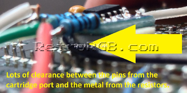
- Solder three 1.2k resistors between the three holes located directly under pin 10 of the cartridge port and a ground point. The picture below shows non-conductive tape covering the components under the resistor, however using heatshrink tubing is a better solution overall.
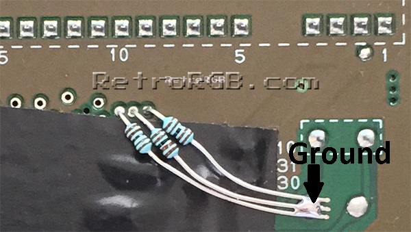
- Flip the motherboard over and trim the extra length of the leads off of the resistors, as they can short to something if not trimmed.