Genesis:Triple Bypass Mod Sega CDX: Difference between revisions
No edit summary |
|||
| Line 47: | Line 47: | ||
[[File:CDX 3BP AudioOutputs.png|CDX 3BP Audio Output Points]] | [[File:CDX 3BP AudioOutputs.png|CDX 3BP Audio Output Points]] | ||
==RGB Video Output Connections== | |||
Connect the 3BP RGB outputs as shown below. If not restoring CVBS, connect the "S75" output pin to the through hole for C46(-). | |||
[[File:CDX 3BP VideoOutputs.png|CDX 3BP RGB Out Connections]] | |||
Revision as of 23:14, 28 November 2022
Top Side Component Removal
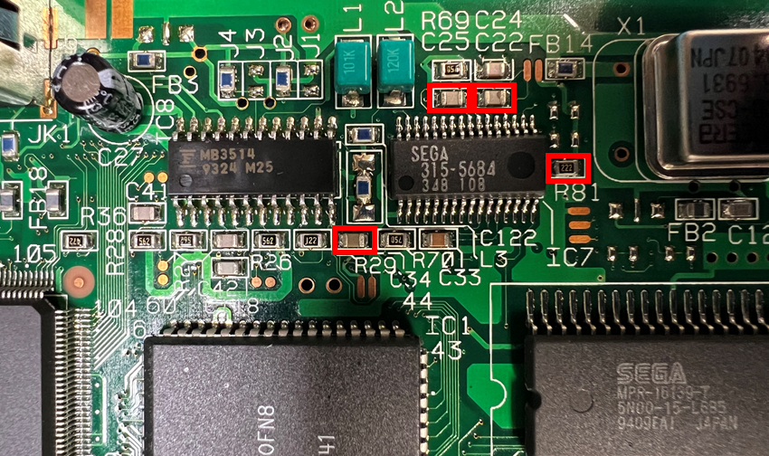
Remove FML, 32X, PSG Components
Remove the components boxed in red below. R81 is optional, but makes connecting PSG easier.
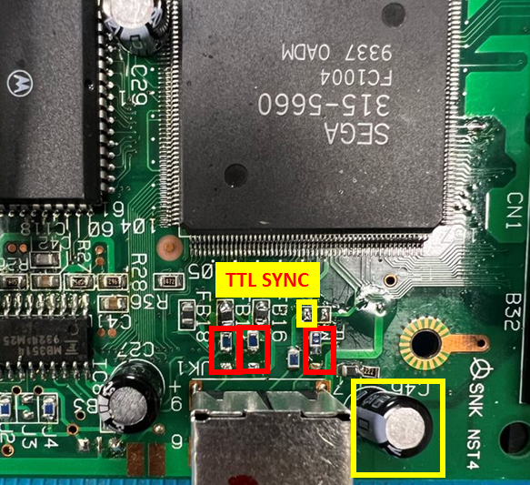
Remove RGB Output Components
Remove the components boxed in red. The components in yellow must be removed if CVBS restoration is not desired.
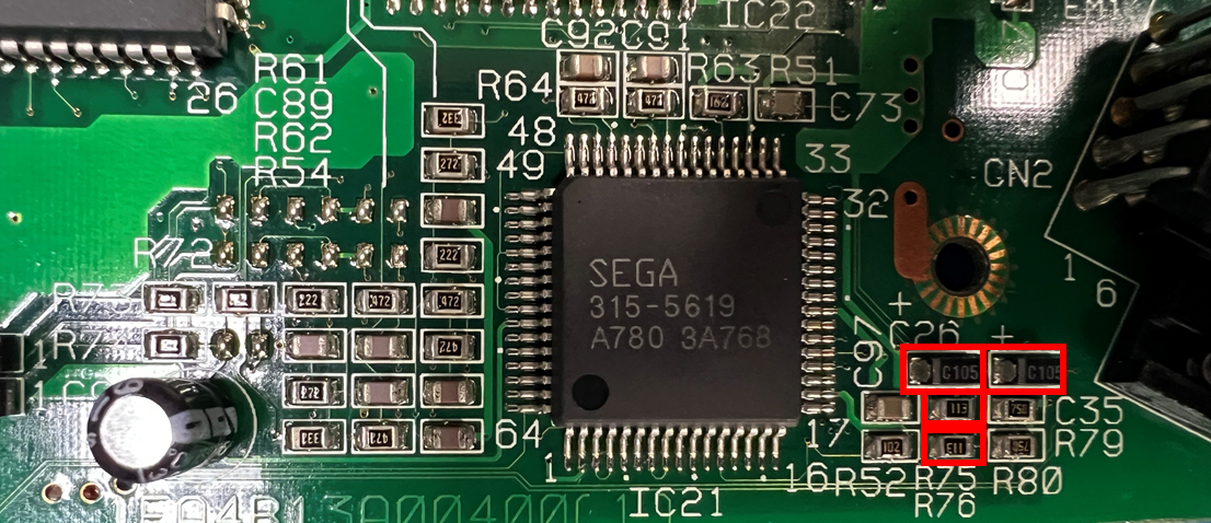
Remove Cart to CD/PCM audio mixing components
Remove the components shown in red, and replace R75 and R76 with 4.7K 0603 or 0805 size 1/8W (or better) resistors.
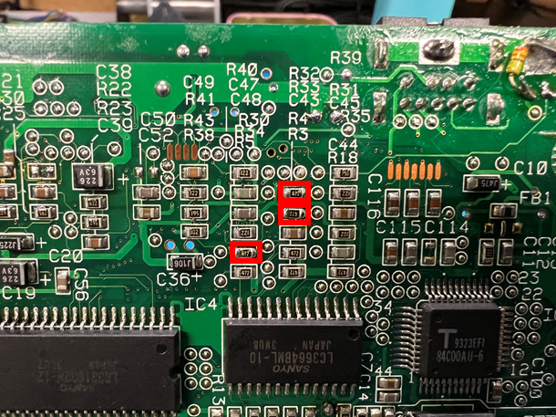
Bottom Side Component Removal
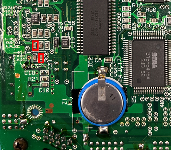
Remove FMR and PSG AC Coupling Capacitors
Remove the components boxed in red.
Remove RGB Encoder Input Resistors
Installation Process
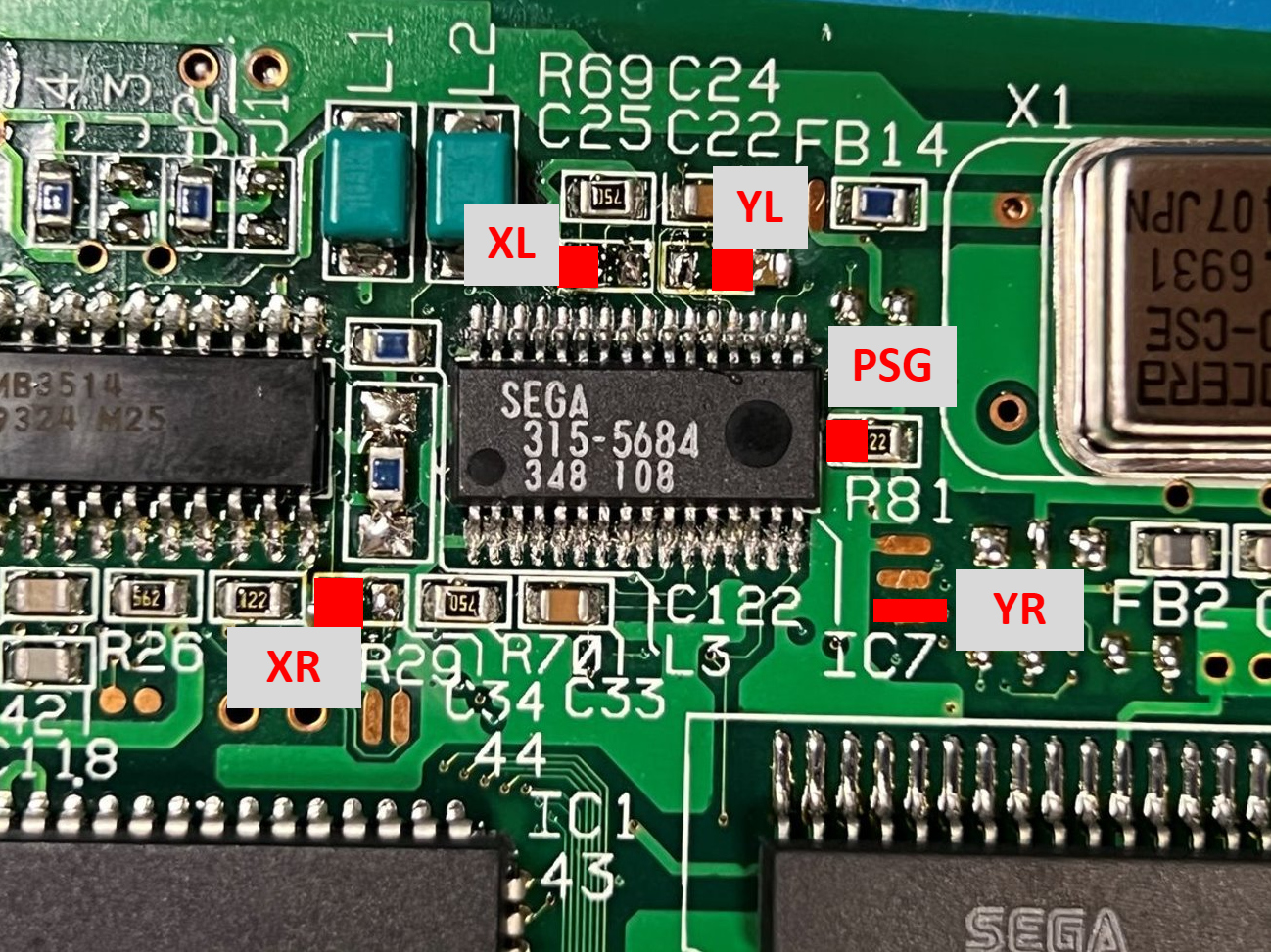
Audio Input Connections
Connect the 3BP audio input pads to the points labeled below. Take note that there is NO input for "CL" or "CR."
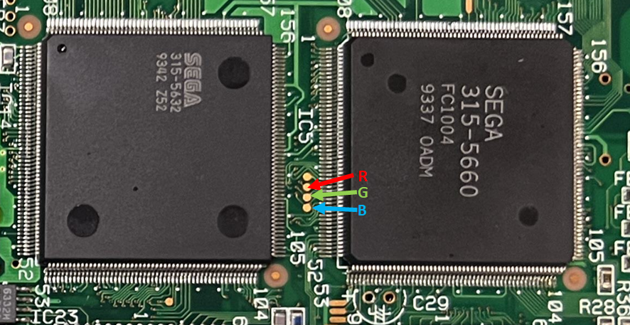
RGB Input Connections
Connect the 3BP RGB input pads to the points labeled below. Refer to the image shown in component removal above for TTL Sync if CVBS restoration is not desired.
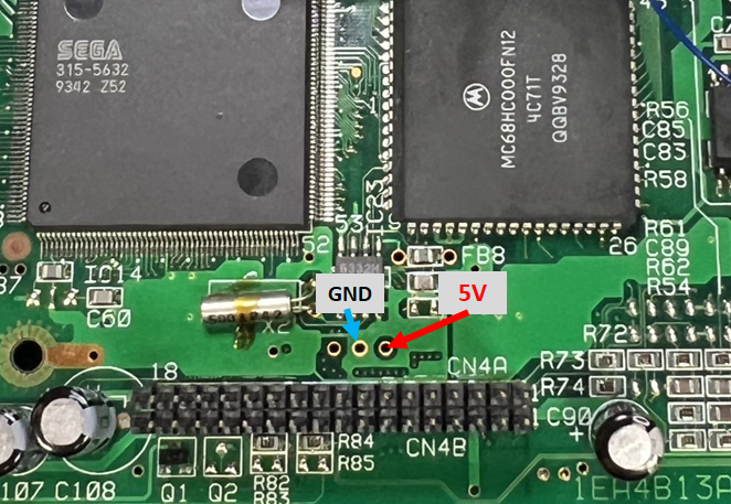
5V and GND Input Connections
Below are suggested connection points for 5V and GND. Other points may also be suitable.
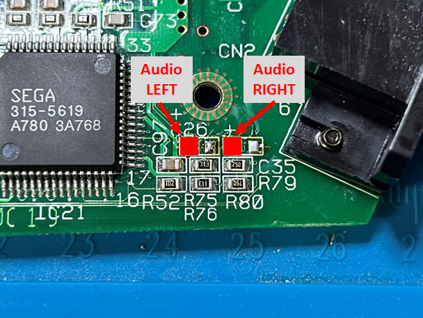
Audio Output Connections
Connect the 3BP Left and Right audio outputs to the points shown below.
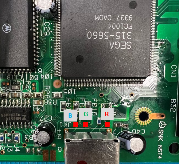
RGB Video Output Connections
Connect the 3BP RGB outputs as shown below. If not restoring CVBS, connect the "S75" output pin to the through hole for C46(-).
