Game Gear:Potentiometer Wheel Replacement: Difference between revisions
Jump to navigation
Jump to search
(WIP) |
No edit summary |
||
| Line 1: | Line 1: | ||
The volume and contrast wheels are common points of failure on Game Gears causing either very quiet volume or a white screen. The | The volume and contrast wheels are common points of failure on Game Gears causing either very quiet/unstable volume or a white screen. | ||
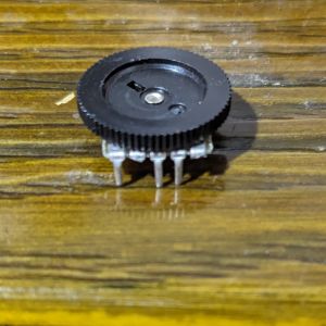
* The volume wheel is a 20KΩ 5-pin potentiometer. It can be replaced with an [https://gamegears4you.com/product/sega-game-gear-sound-board-volume-wheel-potentiometer/ A103 5 pin potentiometer]. | |||
* The contrast wheel is a 20kΩ 4-pin potentiometer. It can be replaced with a 20KΩ B203 3-pin potentiometer or a modified 50KΩ B503 5-pin potentiometer. | |||
== Replacement == | == Replacement == | ||
# Heat the two metal points on the edge of the board and gently lift the potentiometer wheel until the wheel no longer is connected to the edge of the board. Remove the solder from the two edge points. | # Heat the two metal points on the edge of the board and gently lift the broken potentiometer wheel until the wheel no longer is connected to the edge of the board. Remove the solder from the two edge points. | ||
# Use low melt point flux or a hot air station to heat the pins of the potentiometer and remove the wheel. Alternatively, you can clip each leg with flush cutters, then heat and remove each pin. | # Use low melt point flux or a hot air station to heat the pins of the potentiometer and remove the wheel. Alternatively, you can clip each leg with flush cutters, then heat and remove each pin. | ||
# Place the new wheel in position and solder it in place. | # Place the new wheel in position and solder it in place. | ||
| Line 9: | Line 12: | ||
== Modifying a Common Potentiometer == | == Modifying a Common Potentiometer == | ||
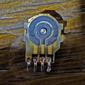
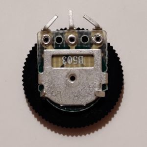
[[File:Game Gear Original Pot.jpg|thumb|The original contrast wheel.]] [[File:Game Gear 5 Pin Pot.jpg|thumb|A modified A103 potentiometer.]] [[File:Game Gear B503 5 Pin Pot.jpg|thumb|A modified B503 potentiometer.]] | |||
Note in the picture to the right how the original potentiometer only has three pins in use and a fourth unused pin. When modifying a potentiometer to fit these pins, the unused pin and the pin next to it should be treated as the same pin and either pin can be used when mounting the wheel (assuming you bridge the two pins together with solder). | |||
If you opted for a 3-pin B203 potentiometer, simply bend the pins to fit the three pin holes. | |||
If you opted for a 5-pin B503 potentiometer, remove pin 2 and pin 4 as shown on the right-hand side and bend the remaining three pins inward to fit the holes on the board. | |||
Revision as of 20:26, 29 October 2023
The volume and contrast wheels are common points of failure on Game Gears causing either very quiet/unstable volume or a white screen.
- The volume wheel is a 20KΩ 5-pin potentiometer. It can be replaced with an A103 5 pin potentiometer.
- The contrast wheel is a 20kΩ 4-pin potentiometer. It can be replaced with a 20KΩ B203 3-pin potentiometer or a modified 50KΩ B503 5-pin potentiometer.
Replacement
- Heat the two metal points on the edge of the board and gently lift the broken potentiometer wheel until the wheel no longer is connected to the edge of the board. Remove the solder from the two edge points.
- Use low melt point flux or a hot air station to heat the pins of the potentiometer and remove the wheel. Alternatively, you can clip each leg with flush cutters, then heat and remove each pin.
- Place the new wheel in position and solder it in place.
Modifying a Common Potentiometer
Note in the picture to the right how the original potentiometer only has three pins in use and a fourth unused pin. When modifying a potentiometer to fit these pins, the unused pin and the pin next to it should be treated as the same pin and either pin can be used when mounting the wheel (assuming you bridge the two pins together with solder).
If you opted for a 3-pin B203 potentiometer, simply bend the pins to fit the three pin holes.
If you opted for a 5-pin B503 potentiometer, remove pin 2 and pin 4 as shown on the right-hand side and bend the remaining three pins inward to fit the holes on the board.


