GBA:Connector Pinouts: Difference between revisions
Jump to navigation
Jump to search
Black Majic (talk | contribs) (Add cartridge pinout) |
CrunchBite (talk | contribs) (Add GBA link cable pinout numbering image) |
||
| (2 intermediate revisions by one other user not shown) | |||
| Line 1: | Line 1: | ||
[[Category:Pinouts]] | [[Category:Pinouts]] | ||
== Cartridge == | == Cartridge == | ||
Pins are numbered left to right, cartridge label up. | Pins are numbered left to right, cartridge label up. There is a switch in the cartridge slot used to differentiate between DMG/CGB and AGB cartridges. When the switch is activated, the pinout is the same as the [[Game_Boy:Connector_Pinouts#Cartridge|Game Boy]]. | ||
{| class="wikitable" | {| class="wikitable" | ||
|- | |- | ||
| Line 25: | Line 25: | ||
|- | |- | ||
| 10 || Data/Address Bit 4 || 20 || Data/Address Bit 14 || 30 || {{overline|CHIP SELECT 2}} | | 10 || Data/Address Bit 4 || 20 || Data/Address Bit 14 || 30 || {{overline|CHIP SELECT 2}} | ||
|} | |||
== GBA SP Power / Headphone Connector == | |||
The GBA SP uses a connector which combines power delivery and audio output. | |||
{| class="wikitable" | |||
|+ EXT.2 | |||
|- | |||
! Pin !! Name !! Description | |||
|- | |||
| 1 || P31 || Left Audio | |||
|- | |||
| 2 || P32 || Supply 5.2v | |||
|- | |||
| 3 || P33 || Right Audio | |||
|- | |||
| 4 || P34 || Audio GND | |||
|- | |||
| 5 || {{ActiveLow|P35}} || Audio Disable | |||
|- | |||
| 6 || P36 || Supply GND | |||
|} | |||
== Link Port == | |||
=== GBA / GBA SP === | |||
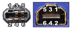
[[File:Gba link cable pinout.png|thumb|GBA link cable pin numbering]] | |||
{| class="wikitable" | |||
|+ EXT / EXT.1 | |||
|- | |||
! Pin !! Name | |||
|- | |||
| 1 || VDD | |||
|- | |||
| 2 || SO | |||
|- | |||
| 3 || SI | |||
|- | |||
| 4 || SD | |||
|- | |||
| 5 || SC | |||
|- | |||
| 6 || GND | |||
|} | |||
=== Micro === | |||
The Game Boy Advance Micro uses a single connector for both power and link cable. | |||
{| class="wikitable" | |||
|+ EXT. | |||
|- | |||
! Pin !! Name | |||
|- | |||
| 1 || Supply 5.2v | |||
|- | |||
| 2 || Serial 3.3v | |||
|- | |||
| 3 || SO | |||
|- | |||
| 4 || SI | |||
|- | |||
| 5 || SD | |||
|- | |||
| 6 || SC | |||
|- | |||
| 7 || Serial GND | |||
|- | |||
| 8 || Supply GND | |||
|} | |} | ||
Latest revision as of 05:43, 17 December 2023
Cartridge
Pins are numbered left to right, cartridge label up. There is a switch in the cartridge slot used to differentiate between DMG/CGB and AGB cartridges. When the switch is activated, the pinout is the same as the Game Boy.
| Pin | Function | Pin | Function | Pin | Function | Pin | Function |
|---|---|---|---|---|---|---|---|
| 01 | +3.3V | 11 | Data/Address Bit 5 | 21 | Data/Address Bit 15 | 31 | IRQ |
| 02 | CLOCK | 12 | Data/Address Bit 6 | 22 | Address Bit 16 | 32 | GROUND |
| 03 | WRITE | 13 | Data/Address Bit 7 | 23 | Address Bit 17 | ||
| 04 | READ | 14 | Data/Address Bit 8 | 24 | Address Bit 18 | ||
| 05 | CHIP SELECT | 15 | Data/Address Bit 9 | 25 | Address Bit 19 | ||
| 06 | Data/Address Bit 0 | 16 | Data/Address Bit 10 | 26 | Address Bit 20 | ||
| 07 | Data/Address Bit 1 | 17 | Data/Address Bit 11 | 27 | Address Bit 21 | ||
| 08 | Data/Address Bit 2 | 18 | Data/Address Bit 12 | 28 | Address Bit 22 | ||
| 09 | Data/Address Bit 3 | 19 | Data/Address Bit 13 | 29 | Address Bit 23 | ||
| 10 | Data/Address Bit 4 | 20 | Data/Address Bit 14 | 30 | CHIP SELECT 2 |
GBA SP Power / Headphone Connector
The GBA SP uses a connector which combines power delivery and audio output.
| Pin | Name | Description |
|---|---|---|
| 1 | P31 | Left Audio |
| 2 | P32 | Supply 5.2v |
| 3 | P33 | Right Audio |
| 4 | P34 | Audio GND |
| 5 | P35 | Audio Disable |
| 6 | P36 | Supply GND |
Link Port
GBA / GBA SP
| Pin | Name |
|---|---|
| 1 | VDD |
| 2 | SO |
| 3 | SI |
| 4 | SD |
| 5 | SC |
| 6 | GND |
Micro
The Game Boy Advance Micro uses a single connector for both power and link cable.
| Pin | Name |
|---|---|
| 1 | Supply 5.2v |
| 2 | Serial 3.3v |
| 3 | SO |
| 4 | SI |
| 5 | SD |
| 6 | SC |
| 7 | Serial GND |
| 8 | Supply GND |
