LaserActive:PAC-S10 FRAM Save RAM Modification: Difference between revisions
No edit summary |
|||
| (5 intermediate revisions by the same user not shown) | |||
| Line 1: | Line 1: | ||
Replacing the Save RAM in the PAC-S10/S1 with an FRAM IC is the same process as the Sega/Mega CD and it's variants. With this modification, the lithium battery is no longer required and can be removed. | Replacing the Save RAM in the PAC-S10/S1 with an FRAM IC is the same process as the Sega/Mega CD and it's variants. With this modification, the lithium battery is no longer required and can be removed. | ||
The SRAM IC reference designator is IC22. Once located, remove the IC using well established practices and replace with either of the following FRAM IC's. | |||
==Using the 64k FM16W08-SG== | ==Using the 64k FM16W08-SG== | ||
| Line 7: | Line 9: | ||
</gallery> | </gallery> | ||
==Using the 256k FM18W08-SG== | ==Using the 256k FM18W08-SG (64K Mode)== | ||
It is also possible to use the 256k variant, but it is necessary to either ground pin 1 or tie it to +5V. The /RESET signal from the battery management IC will be constant during console operation, so it is safe to leave pin 26 as is. The recommended configuration is to simply jump Pin 1 to pin 28. | |||
<gallery> | <gallery> | ||
PACS10 FRAM 256k.jpg|IC22 replaced with 256k FRAM | PACS10 FRAM 256k.jpg|IC22 replaced with 256k FRAM | ||
</gallery> | |||
==256K FM18W08 With Expanded Save RAM Modified BIOS== | |||
Renowned Sega expert Leo Oliveira has discovered how to modify the BIOS code in order to expand the available space for saving games from 64K to 256K. In this scenario, the modified BIOS must be used (not provided here) and loaded either through an Everdrive-type device, or written to an EPROM to replace the on-board BIOS. | |||
===Step 1 - Replace original SRAM=== | |||
Remove the original 64K SRAM and solder the new 256K FRAM IC in its place. | |||
===Step 2 - Connect CPU address signals A14 and A15 to FRAM=== | |||
Connect Pin 1 of the FRAM IC to pin 7 of IC44 | |||
<gallery> | |||
PACS_FRAM_Step 3_ p7.jpg|Pin 7 Connection | |||
</gallery> | |||
Connect pin 26 to pin 17 of IC44. Note: This may also be connected from the top side. | |||
<gallery> | |||
PACS_FRAM_Step 3_p17.jpg|Pin 17 connection | |||
</gallery> | |||
===Step 3 - Lift Pin 10 of IC31=== | |||
IC31 is the battery management IC, located on the bottom of the PAC near the PAC connector, which normally outputs a RESET signal to pin 26 of the Backup RAM IC. Since pin 26 of the FRAM is now addressable by the CPU, the RESET signal needs to be disconnected accordingly. Lift pin 10 of IC31 to disconnect. | |||
<gallery> | |||
PACS_FRAM__IC31.png|IC31 | |||
</gallery> | </gallery> | ||
Latest revision as of 19:37, 31 May 2024
Replacing the Save RAM in the PAC-S10/S1 with an FRAM IC is the same process as the Sega/Mega CD and it's variants. With this modification, the lithium battery is no longer required and can be removed.
The SRAM IC reference designator is IC22. Once located, remove the IC using well established practices and replace with either of the following FRAM IC's.
Using the 64k FM16W08-SG
This part is a direct replacement for the original SRAM IC. Simply replace the IC with the FRAM. No pin lifting necessary.
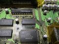
IC22 replaced with 64K FRAM

Using the 256k FM18W08-SG (64K Mode)
It is also possible to use the 256k variant, but it is necessary to either ground pin 1 or tie it to +5V. The /RESET signal from the battery management IC will be constant during console operation, so it is safe to leave pin 26 as is. The recommended configuration is to simply jump Pin 1 to pin 28.
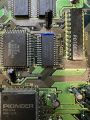
IC22 replaced with 256k FRAM

256K FM18W08 With Expanded Save RAM Modified BIOS
Renowned Sega expert Leo Oliveira has discovered how to modify the BIOS code in order to expand the available space for saving games from 64K to 256K. In this scenario, the modified BIOS must be used (not provided here) and loaded either through an Everdrive-type device, or written to an EPROM to replace the on-board BIOS.
Step 1 - Replace original SRAM
Remove the original 64K SRAM and solder the new 256K FRAM IC in its place.
Step 2 - Connect CPU address signals A14 and A15 to FRAM
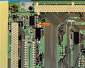
Connect Pin 1 of the FRAM IC to pin 7 of IC44
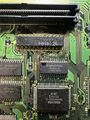
Pin 7 Connection

Connect pin 26 to pin 17 of IC44. Note: This may also be connected from the top side.
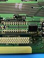
Pin 17 connection

Step 3 - Lift Pin 10 of IC31
IC31 is the battery management IC, located on the bottom of the PAC near the PAC connector, which normally outputs a RESET signal to pin 26 of the Backup RAM IC. Since pin 26 of the FRAM is now addressable by the CPU, the RESET signal needs to be disconnected accordingly. Lift pin 10 of IC31 to disconnect.
IC31
