Genesis:Triple Bypass Mod Model 3 VA2: Difference between revisions
Jump to navigation
Jump to search
No edit summary |
No edit summary |
||
| Line 10: | Line 10: | ||
* '''Proceed at your own risk!''' | * '''Proceed at your own risk!''' | ||
== Tools | == Tools Required == | ||
* Flush cutters | * Flush cutters | ||
* Snips | * Snips | ||
| Line 19: | Line 19: | ||
* 28 or 30 AWG wire | * 28 or 30 AWG wire | ||
== Installation == | |||
$ Start by removing the shell from your console. Remove the 4 screws at the bottom then turn it back upright and lift off the top shell. Remove the screws on the metal shielding and lift the shield off. Next, remove the 2 screws on the sides of the cartridge slot. Now you can lift the motherboard out of the bottom half of the shell. | |||
# Lift the RGB pins (pins 21, 22, and 23) from the CXA1645M chip. <br> [[File:Genesis3VA2_3BPv2_Jose3.jpg|400px]] | # Lift the RGB pins (pins 21, 22, and 23) from the CXA1645M chip. <br> [[File:Genesis3VA2_3BPv2_Jose3.jpg|400px]] | ||
# Solder three wires from these points to the corresponding ones on the Triple Bypass board. <br> [[File:Genesis3VA2 3BPv2 Jose4.png|400px]] | # Solder three wires from these points to the corresponding ones on the Triple Bypass board. <br> [[File:Genesis3VA2 3BPv2 Jose4.png|400px]] | ||
Revision as of 03:29, 15 September 2022
This document will serve as a clear and step-by-step instruction on installing the 3BP on the Genesis Model 3, revision VA2.
WARNINGS
Please read the below warnings before proceeding!
- This guide expects you to have a basic understanding of how to open up your Genesis Model 3 and to have basic soldering skills.
- This mod permanently alters your device.
- This mod should not be done by a beginner and is considered intermediate/advanced.
- Make sure power is disconnected before proceeding.
- After performing this mod you will no longer be able to use composite. You’ll be required to use RGB (or HD Retrovision) cables from this point forward.
- Proceed at your own risk!
Tools Required
- Flush cutters
- Snips
- Soldering iron
- Solder
- Flux
- Solder wick
- 28 or 30 AWG wire
Installation
$ Start by removing the shell from your console. Remove the 4 screws at the bottom then turn it back upright and lift off the top shell. Remove the screws on the metal shielding and lift the shield off. Next, remove the 2 screws on the sides of the cartridge slot. Now you can lift the motherboard out of the bottom half of the shell.
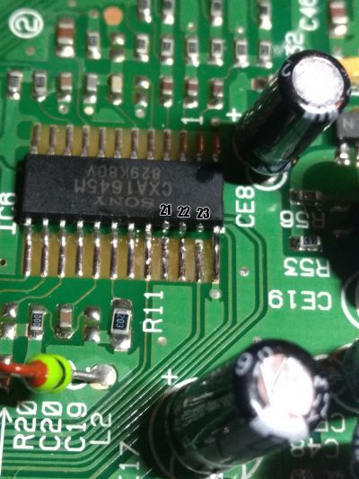
- Lift the RGB pins (pins 21, 22, and 23) from the CXA1645M chip.
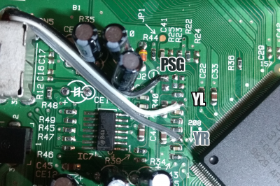
- Solder three wires from these points to the corresponding ones on the Triple Bypass board.
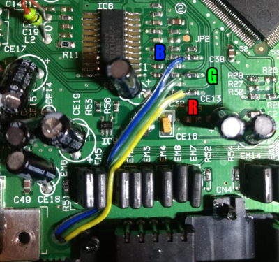
- Solder three wires to the Red, Green, and Blue pads and run them through the hole near the edge of the board and connect them to the Triple Bypass board.
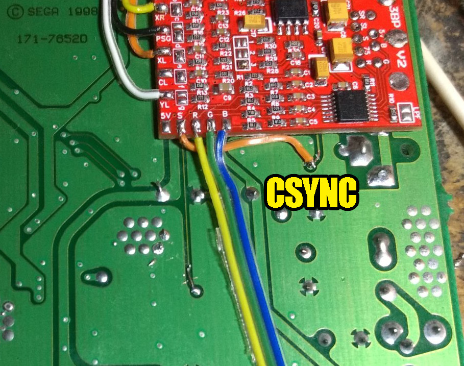
- Solder a wire from the CSYNC point on the board to the sync input on the Triple Bypass board.
- Cut this trace:
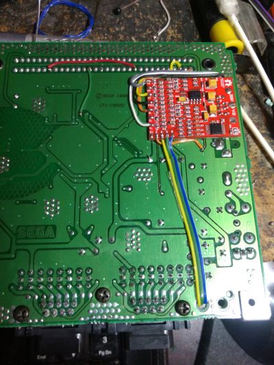
File:Genesis3VA2 3BPv2 Jose6.jpg - The finished product should look like this (see Sega CD Audio section below regarding the pins connected to cartridge connector).
Sega CD Audio
If you are planning on using a Mega SD or Mega EverDrive PRO, you can easily restore Sega CD audio with the instructions found on this page