Master System:M.K Workshop Mark III FM Mod
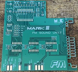
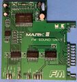
In 2021, a Japanese modder known as M.K Workshop designed an internal FM audio board for the Sega Mark III. It is largely based on the original FM Sound Unit from 1987, and can also be switched off for PSG audio or for games that aren't compatible with the FM Sound Unit. It is meant to be soldered onto the card slot PCB, with only a few extra wires needed for a couple of logic signals and the audio output.
As of 2024, it is only available as a bare PCB and must be assembled before installation in a Mark III. Below is a list of parts needed to assemble one of these boards, most of which can be sourced through distributors such as Digi-Key or Mouser. The only component which must be sourced through other means is the YM2413 itself, as it has been out of production for many years and has become difficult to find in recent years.
Parts List
ICs
- 1x Yamaha YM2413 or YM2413B (can use either the through-hole or SMD versions; make sure to order through a reputable source as fakes can be easily found on eBay or Aliexpress!)
- 1x SOP 74HC4066 quad bilateral switch
- 1x SOP 74LS74 dual D-type flip-flop
- 1x SOP 74LS139 dual 2-to-4 line decoder
- 1x SOP LM358 op-amp
Passives
Note that all resistors and capacitors below 1 uF are 0603 SMD components. Tolerances should be kept around 10% or lower.
- 1x THT 1N4148 diode
- 1x 3.58 MHz crystal/resonator
- 1x SPDT switch
- 2x THT 10 uF 16V electrolytic capacitors
- 1x THT 2.2 uF 50V electrolytic capacitor
- 1x THT 100 uF 16V electrolytic capacitor
- 4x 0.1 uF capacitors
- 2x 33 pF capacitors
- 1x 680 pF capacitor
- 1x 0.01 uF capacitor
- 2x 4.7k ohm resistors
- 2x 3.3k ohm resistors
- 1x 30k ohm resistor
- 1x 15k ohm resistor
- 1x 10k ohm resistor
- 1x 75k ohm resistor
- 1x THT 75 ohm resistor (optional, use this on the audio output if you find the FM is too loud)
Materials and Tools
- JIS/Phillips head screwdriver
- Soldering iron
- Desoldering braid or desoldering braid
- Leaded solder
- Flux (not required but highly recommended)
- Hookup wire
- Flush cutters
- Wire stripper
- Drill with step bits (for on/off switch)
Installation
- Assemble the FM board by soldering in all the components. You can use drag soldering along with plenty of flux
- Flip over the Mark III and remove the six JIS screws. Do not remove the top shell yet as the card slot is screwed into it.
- Carefully maneuver the ribbon cable connecting the card slot PCB to the motherboard and remove the two screws securing the card slot PCB.
- Remove the two screws on the cartridge slot (one on each side) and use a flathead screwdriver or spudger to undo the two bottom catches securing the motherboard to the bottom case. These will require some effort so proceed carefully.
- The cartridge slot will also have a black paper cover placed around it, which hides the internals when the cartridge slot flap is open. Make sure to keep this in a safe place during disassembly.
- On the card slot PCB, there are four solder pads and several solder joints with bent over component leads on them. Use a desoldering tool to remove the excess solder from the pads and a flush cutter to snip off the excess leads. This will ensure that the bottom of the card slot PCB is as flat as possible for the FM board.
- Place the FM board over the card slot PCB so that the solder pads of the FM board are facing the left of the Mark III. The edge of the FM board should line up with the edge of the card slot PCB.
- Solder in the FM board by heating up the solder joints of the card slot and feeding in solder. Make sure not to use too much solder as the spacing between the pads is very thin.
- For the next few steps, you will need to add several wires between the FM board and the Mark III motherboard. Make sure to leave enough slack on these wires for future disassembly.
- Solder two wires from pins 1 and 13 of the 74LS132 chip on the Mark III to the "LS32" pads on the FM board. Pin 1 should be wired to the JOYSEL pad and pin 13 on the KBSEL pad.
- Solder a wire from the +5V VX pad on the FM board to any 5V source on the Mark III motherboard.
- Solder a wire from the audio out pad to the via labeled "AUDIO" on the Mark III motherboard, which is located next to the RF modulator. The FM audio will be injected over both RF and the DIN connector for composite and RGB out.
- If you find that the FM audio is too loud compared to the PSG audio during testing, solder a 75 ohm resistor between the audio output pad and the Mark III.
- Use a small drill bit to make a pilot hole for the FM on/off switch, then use a step bit to drill out the correct size hole for your switch. Wire the center pin of the switch to the center pad for SW1 on the FM board, and wire each end to the ON and OFF pads.
- Place the Mark III motherboard back into the bottom case and reassemble it enough for testing. Use a game which has FM audio for testing. Make sure that both FM and PSG audio are working properly. If both are working, complete reassembly.
- If the FM audio isn't working, double check your wiring and the soldering on the SMD chips.
Links
- Printed instructions which come with the kit
- http://fami-lan.net/parts/pcb.html - Note that the seller does not accept international orders, you will need to order via a proxy service such as Buyee or Zenmarket
- https://www.youtube.com/watch?v=sgE2IR4XRrM


