AV:Sync Stripper: Difference between revisions
(Category:RetroRGB Migration Sourced from [https://www.retrorgb.com/ RetroRGB.com] with explicit permission from Bob.) |
(Removed first person POV) |
||
| (9 intermediate revisions by 2 users not shown) | |||
| Line 1: | Line 1: | ||
This page lists different options to obtain a sync stripper. Please note: You do not need a sync stripper for SCART equipment, but some monitors and BNC switches might require them. Please only use one if you know for a fact you’ll need it. | |||
Generally, a sync stripper may be required if: | |||
* You are using luma sync or sync on composite video with an Extron Crosspoint. | |||
* You are using a NEC XM29 or similar CRT TV. | |||
{{Note|You do not need a sync stripper for SCART equipment! A board like this could be used inside SCART to BNC cables, for things like converting a SCART cable for use with a BNC Extron Crosspoint switch, or a video production monitor that requires TTL sync. Do not use them if you're connecting the cable to a SCART receiving device!}} | |||
You can wire up a small board to use an LM1881 chip to "strip" the sync information from composite video, for use in an RGBs video signal. Please note that the LM1881 outputs TTL-level sync. If you're going into a device that's expecting 75 ohm video-level sync (such as ''ALL'' SCART equipment), then you'll need to add a 470ohm resistor to the output line as noted in the [[AV:Sync_Stripper#75_Ohm_CSYNC_Output|75 Ohm CSYNC Output section at the bottom of this page]]. For more information on sync, see the [[Types of Sync]] page. | |||
== Creating your own Sync Stripper == | |||
[[File:LM1881SOIC01.jpg]] | |||
** | === Required Materials === | ||
* Soldering iron / solder | |||
* Perfboard | |||
* LM1881M chip | |||
* [https://www.adafruit.com/product/1212 8-pin TSOP breakout board] | |||
* One [http://www.digikey.com/product-detail/en/HVR2500006803FR500/PPCQF680KCT-ND/719845 680K resistor] | |||
* Two [http://www.digikey.com/product-detail/en/C320C104J5R5TA7301/399-9867-1-ND/3726105 0.1uf Capacitors] | |||
* One [https://www.digikey.com/product-detail/en/stackpole-electronics-inc/RNMF14FTC470R/S470CACT-ND/2617506 470 ohm, 1/4 watt resistor] (if 75 ohm CSYNC output is needed) | |||
=== Board Assembly === | |||
You can solder the components together directly, but it's recommended to use perfboard as shown in this example to make the circuit. | |||
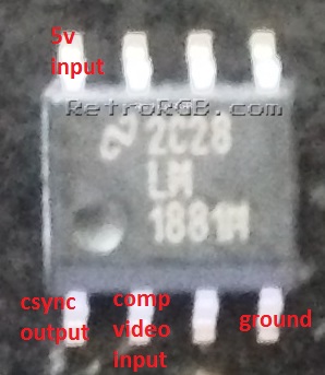
* This is the main LM1881M chip you'll be using (surface-mount, SOIC version) and it's relevant pins: <br> [[File:LM1881SOIC02b.jpg]] | |||
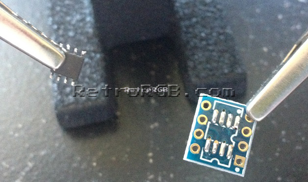
# Start by adding solder to both the chip legs and the pads on the board. <br> [[File:LM1881SOIC03.jpg]] | |||
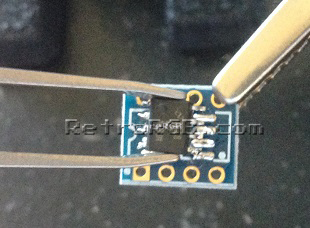
# Use pliers or tweezers to hold the chip while you mount it to the board. <br> [[File:LM1881SOIC04.jpg]] | |||
# When checking, make sure to touch the pin where it enters the chip, not near the bottom where you may accidentally be making contact with the circuit board's pads. Then, touch the other tester to the pad that matches it's input. If a connection isn't made, you could try adding more solder to the joint between the pad and pin: <br> [[File:LM1881SOIC05.jpg]] | |||
# Add a [http://www.digikey.com/product-detail/en/C320C104J5R5TA7301/399-9867-1-ND/3726105 0.1uf capacitor] to the hole that corresponds with pin 2 (composite video in) on the LM1881M. Use a multimeter to double check that the hole on the board matches the pin on the chip: <br> [[File:LM1881SOIC06.jpg]] | |||
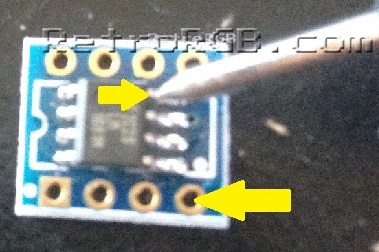
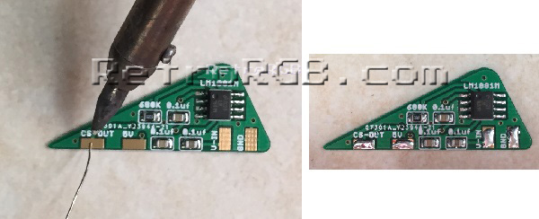
# Add a [http://www.digikey.com/product-detail/en/HVR2500006803FR500/PPCQF680KCT-ND/719845 680K resistor] to the holes corresponding to the arrows below, again using a multimeter to double check the holes to pins between the chip and board. Also, make sure that the resistor isn't touching any of the pins on the chip, or touching the other holes on the board. This one is run above the board to ensure it's not touching: <br> [[File:LM1881SOIC07.jpg]] | |||
# Solder a [http://www.digikey.com/product-detail/en/C320C104J5R5TA7301/399-9867-1-ND/3726105 0.1uf capacitor] to the resistor. Solder it as close to the resistor itself as possible, to make sure it's not touching anything else, or touching to board's pads. <br>[[File:LM1881SOIC08.jpg]] | |||
# Solder power and ground, as well as composite video in / CSYNC out: <br> [[File:LM1881SOIC09.jpg]] | |||
# After you're done, it's good to cover the circuit with heatshrink tubing, so you won't risk shorting it out (or anything else around it). <br> [[File:LM1881SOIC11.jpg]] | |||
If you | Overall, it's pretty easy to make and is a bit smaller then soldering it directly to the chip. The whole set can fit inside a VGA or SCART head for use with equipment that requires TTL-level voltage with a much cleaner look: <br> [[File:LM1881SOIC10.jpg]] | ||
== Sync Stripper in SCART Head == | |||
[[File:SCARTSyncStripper01.jpg]] | |||
If you are using a SCART cable, you can add a Sync-in-SCART board, originally designed by [http://twitter.com/arcadetv Alex a.k.a. ArcadeTV]. This board can be installed anywhere an LM1881 sync stripper is needed, but the provided instructions detail installing it into a SCART head. | |||
Current Sellers: | |||
* [http://store.retrofixes.com/products/premade-lm1881-sync-in-scart-board-kit?rfsn=255623.6664d SNYC-IN-SCART Board, US Seller] | |||
* [https://www.videogameperfection.com/products/sync-in-scart-board/ SNYC-IN-SCART Board, UK Seller] | |||
=== Materials Required === | |||
* The Sync-in-SCART board | |||
* Soldering iron / solder | |||
* Thin wire | |||
* One [https://www.digikey.com/product-detail/en/stackpole-electronics-inc/RNMF14FTC470R/S470CACT-ND/2617506 470 ohm, 1/4 watt resistor] (recommended for safety in case you plug it into a device in SCART applications) | |||
=== Installation === | |||
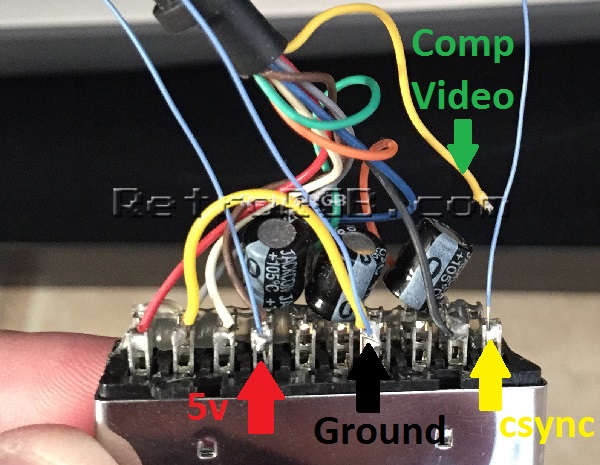
This board can be installed anywhere you need to strip CSYNC from either composite video or luma. For installation inside a console, simply solder (from right to left as shown above) ground, composite video (or luma), 5v power and finally CSYNC output. If mounting inside a console, consider using heat shrink tubing to cover the contacts and ensure nothing can touch it, causing a short. | |||
# Start by adding solder to the 4 pads on the sync-in-SCART board. <br> [[File:SCARTSyncStripper02.jpg]] | |||
# Open the SCART connector and locate the longer row of pins. Also, if your SCART cable came with hot glue covering the pins, carefully remove it before proceeding: <br> [[File:SCARTSyncStripper03.jpg]] | |||
# De-solder the composite video wire that's in pin 20 (the right-most pin in the image below) and solder a short wire in its place. | |||
# Solder a wire to pin 8 (4th from the left in the image below). | |||
# Use a multimeter to find any ground pin and solder a short wire to it. This connector had a separate ground pin that was located just in front of the other pins, making it very easy. <br> [[File:SCARTSyncStripper04.jpg]] | |||
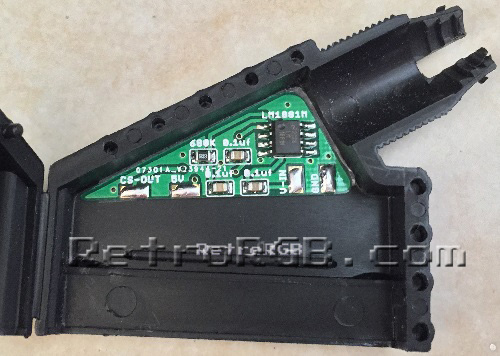
# Add either double-sided tape or glue to the back of the Sync-in-SCART board and affix it to the inside of the SCART connector: <br> [[File:SCARTSyncStripper05.jpg]] | |||
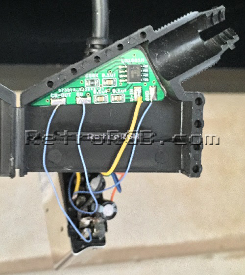
# Next solder all the wires to their corresponding places on the board. | |||
## CS-OUT goes to pin 20 on the SCART connector, the same pin you removed the original composite video wire. | |||
## 5v should connect to the wire you added to pin 8. | |||
## V-IN should be connector to the wire that was originally connected to SCART pin 20. | |||
## GND should be connected to any ground point. <br> [[File:SCARTSyncStripper06.jpg]] | |||
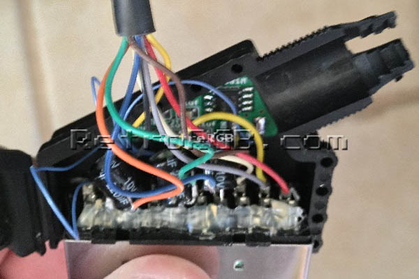
# Carefully re-assemble the SCART connector and make sure no wires get pinched. There is plenty of space inside, but if you're concerned about the Sync-in-SCART board touching anything, feel free to cover it with a piece of non-conductive tape. [[File:SCARTSyncStripper07.jpg]] | |||
== 75 Ohm CSYNC Output == | |||
Please note that this guide shows you how to build the sync stripper circuit; it does NOT talk about use case scenarios. If you're plugging this into ''any'' SCART device, then you'll need to add one [https://www.digikey.com/product-detail/en/stackpole-electronics-inc/RNMF14FTC470R/S470CACT-ND/2617506 470 ohm, 1/4 watt resistor] to attenuate the output to 75 ohm video standards. Many RGB monitors accept a wide variety of sync signals, including the TTL sync that this circuit outputs. If you'd like to be safe, just add the extra resistor; it's literally as easy as just soldering it to the CSYNC output pin. | |||
Latest revision as of 04:19, 2 May 2023
This page lists different options to obtain a sync stripper. Please note: You do not need a sync stripper for SCART equipment, but some monitors and BNC switches might require them. Please only use one if you know for a fact you’ll need it.
Generally, a sync stripper may be required if:
- You are using luma sync or sync on composite video with an Extron Crosspoint.
- You are using a NEC XM29 or similar CRT TV.
| You do not need a sync stripper for SCART equipment! A board like this could be used inside SCART to BNC cables, for things like converting a SCART cable for use with a BNC Extron Crosspoint switch, or a video production monitor that requires TTL sync. Do not use them if you're connecting the cable to a SCART receiving device! |
You can wire up a small board to use an LM1881 chip to "strip" the sync information from composite video, for use in an RGBs video signal. Please note that the LM1881 outputs TTL-level sync. If you're going into a device that's expecting 75 ohm video-level sync (such as ALL SCART equipment), then you'll need to add a 470ohm resistor to the output line as noted in the 75 Ohm CSYNC Output section at the bottom of this page. For more information on sync, see the Types of Sync page.
Creating your own Sync Stripper

Required Materials
- Soldering iron / solder
- Perfboard
- LM1881M chip
- 8-pin TSOP breakout board
- One 680K resistor
- Two 0.1uf Capacitors
- One 470 ohm, 1/4 watt resistor (if 75 ohm CSYNC output is needed)
Board Assembly
You can solder the components together directly, but it's recommended to use perfboard as shown in this example to make the circuit.
- This is the main LM1881M chip you'll be using (surface-mount, SOIC version) and it's relevant pins:

- Start by adding solder to both the chip legs and the pads on the board.
- Use pliers or tweezers to hold the chip while you mount it to the board.
- When checking, make sure to touch the pin where it enters the chip, not near the bottom where you may accidentally be making contact with the circuit board's pads. Then, touch the other tester to the pad that matches it's input. If a connection isn't made, you could try adding more solder to the joint between the pad and pin:
- Add a 0.1uf capacitor to the hole that corresponds with pin 2 (composite video in) on the LM1881M. Use a multimeter to double check that the hole on the board matches the pin on the chip:
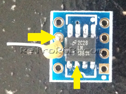
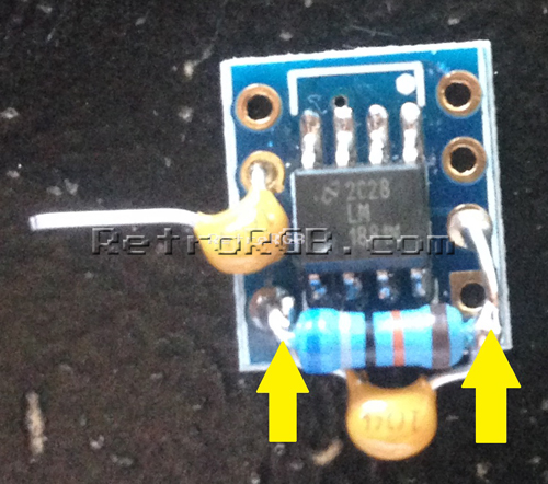
- Add a 680K resistor to the holes corresponding to the arrows below, again using a multimeter to double check the holes to pins between the chip and board. Also, make sure that the resistor isn't touching any of the pins on the chip, or touching the other holes on the board. This one is run above the board to ensure it's not touching:
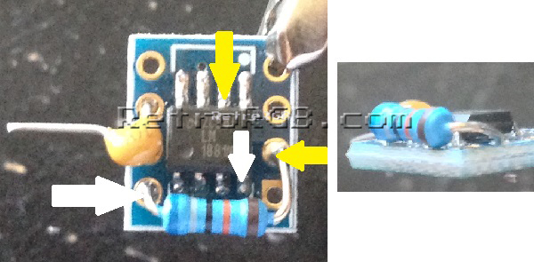
- Solder a 0.1uf capacitor to the resistor. Solder it as close to the resistor itself as possible, to make sure it's not touching anything else, or touching to board's pads.
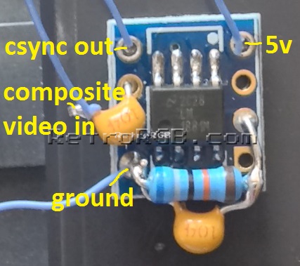
- Solder power and ground, as well as composite video in / CSYNC out:
- After you're done, it's good to cover the circuit with heatshrink tubing, so you won't risk shorting it out (or anything else around it).
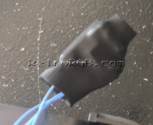


Overall, it's pretty easy to make and is a bit smaller then soldering it directly to the chip. The whole set can fit inside a VGA or SCART head for use with equipment that requires TTL-level voltage with a much cleaner look:

Sync Stripper in SCART Head

If you are using a SCART cable, you can add a Sync-in-SCART board, originally designed by Alex a.k.a. ArcadeTV. This board can be installed anywhere an LM1881 sync stripper is needed, but the provided instructions detail installing it into a SCART head.
Current Sellers:
Materials Required
- The Sync-in-SCART board
- Soldering iron / solder
- Thin wire
- One 470 ohm, 1/4 watt resistor (recommended for safety in case you plug it into a device in SCART applications)
Installation
This board can be installed anywhere you need to strip CSYNC from either composite video or luma. For installation inside a console, simply solder (from right to left as shown above) ground, composite video (or luma), 5v power and finally CSYNC output. If mounting inside a console, consider using heat shrink tubing to cover the contacts and ensure nothing can touch it, causing a short.
- Start by adding solder to the 4 pads on the sync-in-SCART board.
- Open the SCART connector and locate the longer row of pins. Also, if your SCART cable came with hot glue covering the pins, carefully remove it before proceeding:
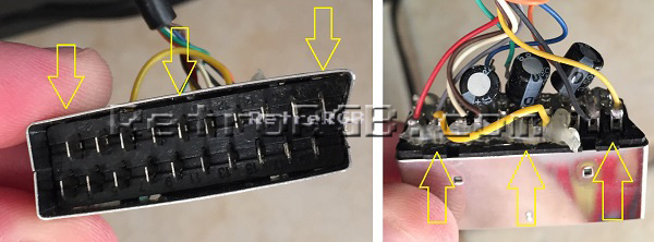
- De-solder the composite video wire that's in pin 20 (the right-most pin in the image below) and solder a short wire in its place.
- Solder a wire to pin 8 (4th from the left in the image below).
- Use a multimeter to find any ground pin and solder a short wire to it. This connector had a separate ground pin that was located just in front of the other pins, making it very easy.
- Add either double-sided tape or glue to the back of the Sync-in-SCART board and affix it to the inside of the SCART connector:
- Next solder all the wires to their corresponding places on the board.
- CS-OUT goes to pin 20 on the SCART connector, the same pin you removed the original composite video wire.
- 5v should connect to the wire you added to pin 8.
- V-IN should be connector to the wire that was originally connected to SCART pin 20.
- GND should be connected to any ground point.
- Carefully re-assemble the SCART connector and make sure no wires get pinched. There is plenty of space inside, but if you're concerned about the Sync-in-SCART board touching anything, feel free to cover it with a piece of non-conductive tape.


75 Ohm CSYNC Output
Please note that this guide shows you how to build the sync stripper circuit; it does NOT talk about use case scenarios. If you're plugging this into any SCART device, then you'll need to add one 470 ohm, 1/4 watt resistor to attenuate the output to 75 ohm video standards. Many RGB monitors accept a wide variety of sync signals, including the TTL sync that this circuit outputs. If you'd like to be safe, just add the extra resistor; it's literally as easy as just soldering it to the CSYNC output pin.