CD-i:CD-i 220 RGB Mod: Difference between revisions
Jump to navigation
Jump to search
No edit summary |
No edit summary |
||
| Line 1: | Line 1: | ||
As long as your NTSC CDi has the Sony CXA chip, this mod will work. PAL 220 boards should have the RGB SCART built-in. | |||
As long as your NTSC CDi has the Sony CXA chip, this mod will work. PAL 220 | |||
== Required Materials == | |||
You'll need a few tools for this mod | You'll need a few tools for this mod: | ||
* Soldering skills | |||
* Torx screwdriver set to open the CDi case and internals | |||
* Philips head screwdriver | |||
* Soldering iron / solder | |||
* Thin gauge wire | |||
* [http://www.digikey.com/product-detail/en/MRS25000C7509FRP00/PPC75.0ZCT-ND/595092 Four (4) 75 Ohm resistors, the lowest tolerance possible]. | |||
* [https://www.digikey.com/product-detail/en/nichicon/USR1C221MDD/493-15996-ND/2539210 Four (4) 220uF/16v capacitors] | |||
* RGB output port (any port will work, just make sure you pick a port with a matching RGB cable). | |||
== Instructions == | |||
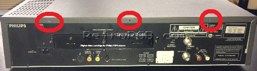
Start by removing the top cover: Remove the two torx screws on each side and the top three screws in back: <br>[[File:CDiRGB01.jpg]] | # Start by removing the top cover: Remove the two torx screws on each side and the top three screws in back: <br> [[File:CDiRGB01.jpg]] | ||
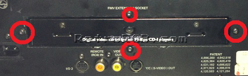
# Next, remove the outer screws that contain the expansion socket. These screws were one size larger torx than the case screws: <br> [[File:CDiRGB02.jpg]] | |||
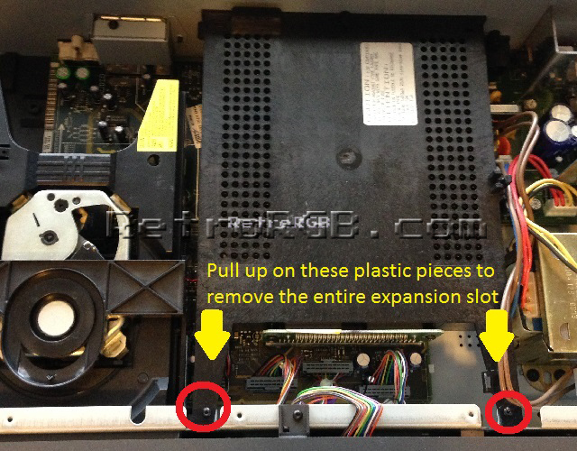
# Before you can remove the expansion socket, remove the two screws on top, then pull up from the area by the top screws to release the socket: <br> [[File:CDiRGB04.jpg]] | |||
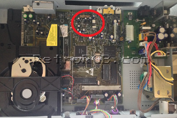
# You'll find the Sony CXA chip underneath the expansion slot: <br> [[File:CDiRGB05.jpg]] | |||
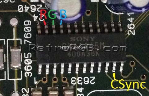
# Solder R, G, B and CSYNC (please see the note about csync below) directly to the chip, as shown here: <br> [[File:CDiRGB06.jpg]] | |||
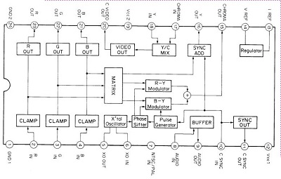
# Here's the actual chip diagram, in case you're interested (click for full-sized): <br> [[File:CDiRGB07.jpg]] | |||
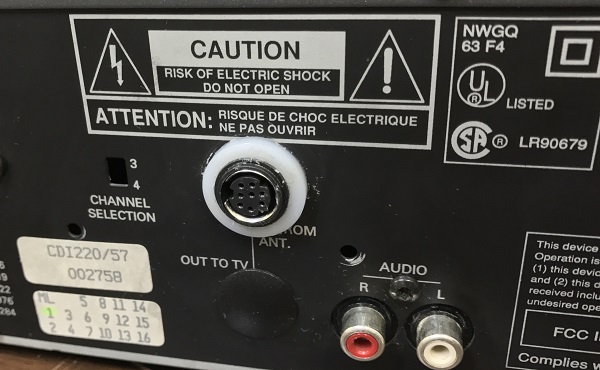
# Next, choose a mounting location for your RGB port. It's recommended to use an 8-pin MiniDIN and mounted it where the RF adapter went, allowing the mod to be 100% reversible, without any cutting at all. <br> [[File:CDiRGB11.jpg]] | |||
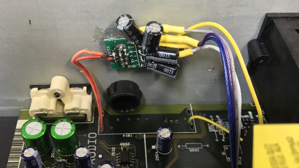
# Run all four video lines to the output. Make sure each line has a 220uF/16v capacitor on the end, as well as a [http://www.digikey.com/product-detail/en/MRS25000C7509FRP00/PPC75.0ZCT-ND/595092 75ohm] resistor on each line as well. <br> [[File:CDiRGB12.jpg]] | |||
# Find a ground point to solder to your connector. There's no "special" place to get ground, anywhere will do (just verify with your multimeter). | |||
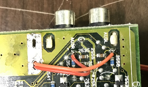
# If your RGB connector routes audio through it, wire that in as well: <br> [[File:CDiRGB13.jpg]] | |||
Results: <br> [[File:CDiRGB14.jpg]] | |||
Revision as of 17:01, 3 July 2022
As long as your NTSC CDi has the Sony CXA chip, this mod will work. PAL 220 boards should have the RGB SCART built-in.
Required Materials
You'll need a few tools for this mod:
- Soldering skills
- Torx screwdriver set to open the CDi case and internals
- Philips head screwdriver
- Soldering iron / solder
- Thin gauge wire
- Four (4) 75 Ohm resistors, the lowest tolerance possible.
- Four (4) 220uF/16v capacitors
- RGB output port (any port will work, just make sure you pick a port with a matching RGB cable).
Instructions
- Start by removing the top cover: Remove the two torx screws on each side and the top three screws in back:
- Next, remove the outer screws that contain the expansion socket. These screws were one size larger torx than the case screws:
- Before you can remove the expansion socket, remove the two screws on top, then pull up from the area by the top screws to release the socket:
- You'll find the Sony CXA chip underneath the expansion slot:
- Solder R, G, B and CSYNC (please see the note about csync below) directly to the chip, as shown here:
- Here's the actual chip diagram, in case you're interested (click for full-sized):
- Next, choose a mounting location for your RGB port. It's recommended to use an 8-pin MiniDIN and mounted it where the RF adapter went, allowing the mod to be 100% reversible, without any cutting at all.
- Run all four video lines to the output. Make sure each line has a 220uF/16v capacitor on the end, as well as a 75ohm resistor on each line as well.
- Find a ground point to solder to your connector. There's no "special" place to get ground, anywhere will do (just verify with your multimeter).
- If your RGB connector routes audio through it, wire that in as well:


Results:
