Genesis:Triple Bypass Mod Model 3 VA1: Difference between revisions
Jump to navigation
Jump to search
(→Installation: Trace cut) |
|||
| Line 23: | Line 23: | ||
# Start by removing the shell from your console. Remove the 4 screws at the bottom then turn it back upright and lift off the top shell. Remove the screws on the metal shielding and lift the shield off. Next, remove the 2 screws on the sides of the cartridge slot. Now you can lift the motherboard out of the bottom half of the shell. | # Start by removing the shell from your console. Remove the 4 screws at the bottom then turn it back upright and lift off the top shell. Remove the screws on the metal shielding and lift the shield off. Next, remove the 2 screws on the sides of the cartridge slot. Now you can lift the motherboard out of the bottom half of the shell. | ||
# Cut this trace and verify with a multimeter that there is no continuity between the two points. <br> [[File:Genesis_3_3BP_Bottom_Trace_Cut.png]] | |||
# Mount the bypass board on the top of the motherboard. The recommended spot is on the right-hand side on the large solder joints sticking up. | # Mount the bypass board on the top of the motherboard. The recommended spot is on the right-hand side on the large solder joints sticking up. | ||
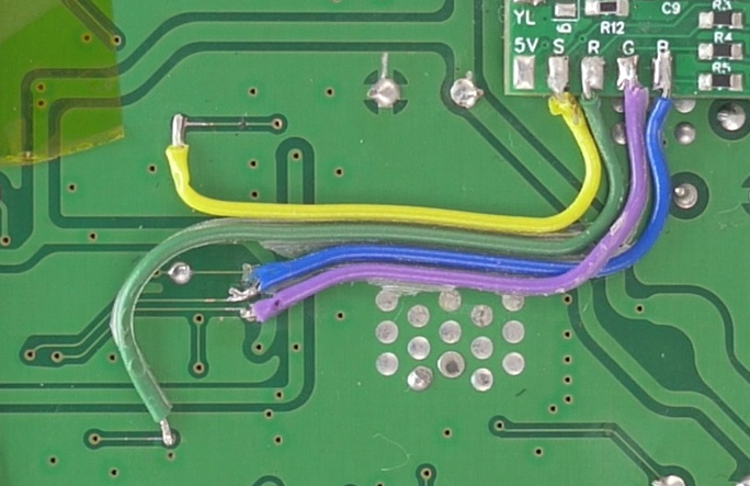
# Solder wires from the video signals (RGBS) pads on the bypass board to the vias shown here. [[File:Genesis 3 VA1 3BP RGBS.png]] | # Solder wires from the video signals (RGBS) pads on the bypass board to the vias shown here. [[File:Genesis 3 VA1 3BP RGBS.png]] | ||
Revision as of 04:27, 25 October 2022
This document will serve as clear step-by-step instructions for installing the 3BP on the Genesis Model 3, revision VA1.
Warnings
Please read the below warnings before proceeding!
- This guide expects you to have a basic understanding of how to open up your Genesis Model 3 and to have basic soldering skills.
- This mod permanently alters your device.
- This mod should not be done by a beginner and is considered intermediate/advanced.
- Make sure power is disconnected before proceeding.
- After performing this mod you will no longer be able to use composite. You’ll be required to use RGB (or HD Retrovision) cables from this point forward.
- Proceed at your own risk!
Tools Required
- Flush cutters
- Snips
- Soldering iron
- Solder
- Flux
- Solder wick
- 28 or 30 AWG wire
Installation

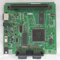
The top of the motherboard post-modification (green wires are the Sega CD audio fix).

- Start by removing the shell from your console. Remove the 4 screws at the bottom then turn it back upright and lift off the top shell. Remove the screws on the metal shielding and lift the shield off. Next, remove the 2 screws on the sides of the cartridge slot. Now you can lift the motherboard out of the bottom half of the shell.
- Cut this trace and verify with a multimeter that there is no continuity between the two points.
File:Genesis 3 3BP Bottom Trace Cut.png - Mount the bypass board on the top of the motherboard. The recommended spot is on the right-hand side on the large solder joints sticking up.
- Solder wires from the video signals (RGBS) pads on the bypass board to the vias shown here.
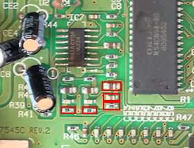
- Remove these five components from the motherboard.
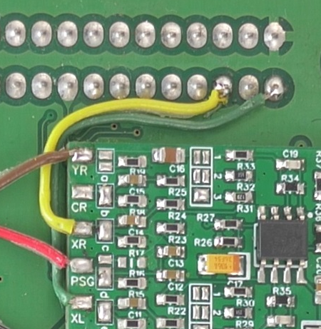
- Solder wires from the audio signals (YL/YR/PSG) pads on the bypass board to these resistors on the bottom side of the motherboard, snaking the wires through the controller ports to the top side of the motherboard.

- Solder wires from the audio signal output (XL/XR) pads on the bypass board to the cart connectors pins B1 (XL) and B3 (XR).


Post-Installation Fixes
If you are planning on using a Mega SD or Mega EverDrive PRO, you can easily restore Sega CD audio with the instructions found on this page.
If you followed this guide and lifted the RGB pins, you may want to apply this simple fix for the color.