Intellivision:System Changer Modification: Difference between revisions
(Created page with "Category:Intellivision '''Most page content & researching taken from [http://wiki.intellivision.us/index.php/Intellivision_System_Changer_Support_Modification the procedure on the Intellivision Wiki], which was released to the public domain by its author, Intelligoth, in 2007. The procedure has been edited for prose, grammar and clarity.''' The Intellivision System Changer was released in 1983 by Mattel Electronics as a way for Intellivision owners to play Atari 260...") |
m (→Procedure) |
||
| (11 intermediate revisions by the same user not shown) | |||
| Line 2: | Line 2: | ||
'''Most page content & researching taken from [http://wiki.intellivision.us/index.php/Intellivision_System_Changer_Support_Modification the procedure on the Intellivision Wiki], which was released to the public domain by its author, Intelligoth, in 2007. The procedure has been edited for prose, grammar and clarity.''' | '''Most page content & researching taken from [http://wiki.intellivision.us/index.php/Intellivision_System_Changer_Support_Modification the procedure on the Intellivision Wiki], which was released to the public domain by its author, Intelligoth, in 2007. The procedure has been edited for prose, grammar and clarity.''' | ||
The Intellivision System Changer was released in 1983 by Mattel Electronics as a way for Intellivision owners to play Atari 2600 games without connecting another console. It is essentially an entire 2600 clone which uses the Intellivision for AV output and power, and can even make use of the Intellivision's own controllers. However, it is only compatible with the cost-reduced Intellivision II and does not work on any other Intellivision console (including licensed clones such as the Sears Super Video Arcade and Tandyvision One) due to them not having a composite video input on their cartridge port. Fortunately, it is possible to modify these consoles to accept video input from the System Changer, and this modification was even offered by Mattel for a short time. | The Intellivision System Changer was released in 1983 by Mattel Electronics as a way for Intellivision owners to play Atari 2600 games without connecting another console. It is essentially an entire 2600 clone which uses the Intellivision for AV output and power, and can even make use of the Intellivision's own controllers. However, it is only compatible with the cost-reduced Intellivision II and does not work on any other Intellivision console (including licensed clones such as the Sears Super Video Arcade and Tandyvision One) due to them not having a suitable composite video input on their cartridge port. Fortunately, it is possible to modify these consoles to accept video input from the System Changer, and this exact modification was even offered by Mattel for a short time. | ||
Note that this modification does '''not''' work with RGB mods such as the Yannick or Orange Peel/Crayola King boards as they tap from the Intellivision | Note that this modification does '''not''' work with RGB mods such as the Yannick or Orange Peel/Crayola King boards as they tap from the Intellivision's color processor chip, and not from the composite video feed going into the RF modulator. It is designed to work with the original RF output, but will also work with composite video mods which tap video from the RF modulator. | ||
==Materials and Tools== | ==Materials and Tools== | ||
| Line 11: | Line 11: | ||
**Two 1N914 diodes or equivalents | **Two 1N914 diodes or equivalents | ||
**Hookup wire | **Hookup wire | ||
*Tools | *Tools | ||
**Phillips head screwdriver | **Phillips head screwdriver | ||
| Line 19: | Line 18: | ||
**Desoldering braid | **Desoldering braid | ||
**Needlenose pliers | **Needlenose pliers | ||
**Razor blade | |||
==Procedure== | ==Procedure== | ||
Please ensure that the Intellivision is completely unplugged before proceeding, as the Intellivision has an internal power supply with line voltage present. | Please ensure that the Intellivision is completely unplugged before proceeding, as the Intellivision has an internal power supply with line voltage present. Note that component names (i.e. R23, R24) refer to the Intellivision schematic and are not silkscreened on the board. The install photos below also serve as a reference. | ||
# Turn the Intellivision upside down and remove the six Phillips screws from the base of the unit chassis. | # Turn the Intellivision upside down and remove the six Phillips screws from the base of the unit chassis. | ||
# Carefully turn the unit right side up again and remove the power switch cover, which lifts right off. Remove the top half of the Intellivision chassis. | # Carefully turn the unit right side up again and remove the power switch cover, which lifts right off. Remove the top half of the Intellivision chassis, feeding the controllers through as you lift it off. | ||
# Remove the six Phillips screws that secure the | # Remove the six Phillips screws that secure the controller tray. Keep these screws separate from the chassis screws. Lift the controller tray up and set it aside. | ||
#*For the Sears Super Video Arcade, also remove the controller ports by carefully pulling back the retaining tabs on the tray and leaning the ports back. | |||
# Disconnect the 5 pin white ribbon cable (wiggle it up slowly) connecting the Logic Board Module (encased in a metal RF shroud) to the power supply board. Be careful not to touch the large capacitors on the power supply board, as they can hold an electric charge. Use a felt pen and mark the orientation of the ribbon cable with its socket to ensure proper orientation on re-assembly. | # Disconnect the 5 pin white ribbon cable (wiggle it up slowly) connecting the Logic Board Module (encased in a metal RF shroud) to the power supply board. Be careful not to touch the large capacitors on the power supply board, as they can hold an electric charge. Use a felt pen and mark the orientation of the ribbon cable with its socket to ensure proper orientation on re-assembly. | ||
#* This particular cable is ''extremely'' fragile and can disintegrate due to age, so be very careful when handling it. | |||
# Disconnect the blue cable above the 5 pin ribbon cable. Again, use a felt pen to mark its orientation. | # Disconnect the blue cable above the 5 pin ribbon cable. Again, use a felt pen to mark its orientation. | ||
# | # Lift the Logic Board Module from the bottom shell of the Intellivision. Disconnect the cables for the controllers. Again, use a felt pen to mark the orientation of the controller cable connectors. The brown wire of each connector goes to pin 1 (topmost pin). | ||
# The logic board is sandwiched between two metal RF shields that are secured by solder points. Heat up the solder points until the solder melts, then use desoldering braid or a solder sucker to remove the solder. | # The logic board is sandwiched between two metal RF shields that are secured by solder points. Heat up the solder points until the solder melts, then use desoldering braid or a solder sucker to remove the solder. There is a large amount of solder securing these points so take your time. | ||
# Remove the shielding so that you are left with the exposed logic board. | # Remove the shielding so that you are left with the exposed logic board. | ||
# Flip over the logic board so the components are on top. Remove the 300 ohm resistor at R23 and the 3K ohm resistor at R24 by desoldering them from the board or snipping them out. | # Flip over the logic board so the components are on top. Remove the 300 ohm resistor at R23 (Fig. 1) and the 3K ohm resistor at R24 (Fig. 2) by desoldering them from the board or snipping them out (Fig. 3). | ||
# Cut the trace at the pad for R24 that leads to pin 1 of the RF modulator (the pin furthest away from the edge of the motherboard). | # Cut the trace at the pad for R24 that leads to pin 1 of the RF modulator (the pin furthest away from the edge of the motherboard, Fig. 4). | ||
# Solder a 1N914 diode with the cathode (striped end) on the pad for R24 and the anode on the trace leading to pin 1 of the RF modulator. | # Solder a 1N914 diode with the cathode (striped end) on the pad for R24 and the anode on the trace leading to pin 1 of the RF modulator. | ||
# Solder the second diode with the cathode at the pad for C33 connected to R3 and solder the anode onto the anode of the first diode. | # Solder the second diode with the cathode at the pad for C33 connected to R3 and solder the anode onto the anode of the first diode. | ||
# Solder a 2" length of wire from the cathode of diode CR8 to the junction connecting resistors R3 and R9. | # Solder a 2" length of wire from the cathode of diode CR8 to the junction connecting resistors R3 and R9. | ||
# Flip over the logic board so the traces are on top. | # Flip over the logic board so the traces are on top. | ||
# Cut the trace at the pad for resistor R3 going to pin 1 of the RF modulator, then cut the trace connected to pin 2 of the cartridge port. | # Cut the trace at the pad for resistor R3 going to pin 1 of the RF modulator (Fig. 5), then cut the trace connected to pin 2 of the cartridge port (Fig. 6). | ||
#* Some boards have an additional trace on the component side going between pins 1 and 2 of the cartridge port. If this trace is present, it will need to be cut as well. | #* Some boards have an additional trace on the component side going between pins 1 and 2 of the cartridge port. If this trace is present, it will need to be cut as well. | ||
# | # Solder one end of another wire to the pad of R24 where you previously soldered the cathode of the first diode. (Fig. 7) | ||
# | # Solder the other end of the wire to pin 2 of the cartridge port (Fig. 8). | ||
# Reassemble the Intellivision to the point where it can be tested with the System Changer. If the test is successful, fully reassemble the console. | # Reassemble the Intellivision to the point where it can be tested with the System Changer. If the test is successful, fully reassemble the console. | ||
<gallery> | |||
Image:IntellivisionR23.jpg|Fig. 1 - The first resistor that must be removed is R23 (300 ohm). | |||
Image:IntellivisionR24.jpg|Fig. 2 - The next resistor to remove is R24 (3K ohm). | |||
Image:IntellivisionR23and24removed.jpg|Fig. 3 - Both resistors have now been removed and the board is ready for trace cuts. | |||
Image:IntellivisionR24tracecut.JPG|Fig. 4 - The trace connecting R24 to pin 1 of the RF modulator has been cut. | |||
Image:Intellivisionjunctioncut.JPG|Fig. 5 - The trace connecting R3 to pin 1 of the modulator has been cut. | |||
Image:Intellivisionpin2tracecut.jpg|Fig. 6 - Pin 2 on the cartridge port is connected to GND and must be cut, as shown here. | |||
Image:Intellivisionvideoin.JPG|Fig. 7 - This wire connects the video coming in... | |||
Image:Intellivisionvideopin2.JPG|Fig. 8 - ...from the System Changer on pin 2 of the cartridge port. | |||
Image:Intellivisioncompletemod.jpg|Fig. 9 - The completed modification on the component side. | |||
</gallery> | |||
Latest revision as of 18:09, 20 October 2023
Most page content & researching taken from the procedure on the Intellivision Wiki, which was released to the public domain by its author, Intelligoth, in 2007. The procedure has been edited for prose, grammar and clarity.
The Intellivision System Changer was released in 1983 by Mattel Electronics as a way for Intellivision owners to play Atari 2600 games without connecting another console. It is essentially an entire 2600 clone which uses the Intellivision for AV output and power, and can even make use of the Intellivision's own controllers. However, it is only compatible with the cost-reduced Intellivision II and does not work on any other Intellivision console (including licensed clones such as the Sears Super Video Arcade and Tandyvision One) due to them not having a suitable composite video input on their cartridge port. Fortunately, it is possible to modify these consoles to accept video input from the System Changer, and this exact modification was even offered by Mattel for a short time.
Note that this modification does not work with RGB mods such as the Yannick or Orange Peel/Crayola King boards as they tap from the Intellivision's color processor chip, and not from the composite video feed going into the RF modulator. It is designed to work with the original RF output, but will also work with composite video mods which tap video from the RF modulator.
Materials and Tools
- Materials
- Leaded solder
- Two 1N914 diodes or equivalents
- Hookup wire
- Tools
- Phillips head screwdriver
- Soldering iron
- Wire strippers
- Flush cutters
- Desoldering braid
- Needlenose pliers
- Razor blade
Procedure
Please ensure that the Intellivision is completely unplugged before proceeding, as the Intellivision has an internal power supply with line voltage present. Note that component names (i.e. R23, R24) refer to the Intellivision schematic and are not silkscreened on the board. The install photos below also serve as a reference.
- Turn the Intellivision upside down and remove the six Phillips screws from the base of the unit chassis.
- Carefully turn the unit right side up again and remove the power switch cover, which lifts right off. Remove the top half of the Intellivision chassis, feeding the controllers through as you lift it off.
- Remove the six Phillips screws that secure the controller tray. Keep these screws separate from the chassis screws. Lift the controller tray up and set it aside.
- For the Sears Super Video Arcade, also remove the controller ports by carefully pulling back the retaining tabs on the tray and leaning the ports back.
- Disconnect the 5 pin white ribbon cable (wiggle it up slowly) connecting the Logic Board Module (encased in a metal RF shroud) to the power supply board. Be careful not to touch the large capacitors on the power supply board, as they can hold an electric charge. Use a felt pen and mark the orientation of the ribbon cable with its socket to ensure proper orientation on re-assembly.
- This particular cable is extremely fragile and can disintegrate due to age, so be very careful when handling it.
- Disconnect the blue cable above the 5 pin ribbon cable. Again, use a felt pen to mark its orientation.
- Lift the Logic Board Module from the bottom shell of the Intellivision. Disconnect the cables for the controllers. Again, use a felt pen to mark the orientation of the controller cable connectors. The brown wire of each connector goes to pin 1 (topmost pin).
- The logic board is sandwiched between two metal RF shields that are secured by solder points. Heat up the solder points until the solder melts, then use desoldering braid or a solder sucker to remove the solder. There is a large amount of solder securing these points so take your time.
- Remove the shielding so that you are left with the exposed logic board.
- Flip over the logic board so the components are on top. Remove the 300 ohm resistor at R23 (Fig. 1) and the 3K ohm resistor at R24 (Fig. 2) by desoldering them from the board or snipping them out (Fig. 3).
- Cut the trace at the pad for R24 that leads to pin 1 of the RF modulator (the pin furthest away from the edge of the motherboard, Fig. 4).
- Solder a 1N914 diode with the cathode (striped end) on the pad for R24 and the anode on the trace leading to pin 1 of the RF modulator.
- Solder the second diode with the cathode at the pad for C33 connected to R3 and solder the anode onto the anode of the first diode.
- Solder a 2" length of wire from the cathode of diode CR8 to the junction connecting resistors R3 and R9.
- Flip over the logic board so the traces are on top.
- Cut the trace at the pad for resistor R3 going to pin 1 of the RF modulator (Fig. 5), then cut the trace connected to pin 2 of the cartridge port (Fig. 6).
- Some boards have an additional trace on the component side going between pins 1 and 2 of the cartridge port. If this trace is present, it will need to be cut as well.
- Solder one end of another wire to the pad of R24 where you previously soldered the cathode of the first diode. (Fig. 7)
- Solder the other end of the wire to pin 2 of the cartridge port (Fig. 8).
- Reassemble the Intellivision to the point where it can be tested with the System Changer. If the test is successful, fully reassemble the console.
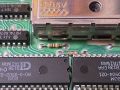
Fig. 1 - The first resistor that must be removed is R23 (300 ohm).
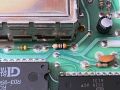
Fig. 2 - The next resistor to remove is R24 (3K ohm).
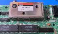
Fig. 3 - Both resistors have now been removed and the board is ready for trace cuts.
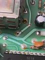
Fig. 4 - The trace connecting R24 to pin 1 of the RF modulator has been cut.
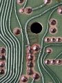
Fig. 5 - The trace connecting R3 to pin 1 of the modulator has been cut.
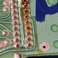
Fig. 6 - Pin 2 on the cartridge port is connected to GND and must be cut, as shown here.
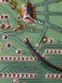
Fig. 7 - This wire connects the video coming in...
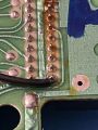
Fig. 8 - ...from the System Changer on pin 2 of the cartridge port.
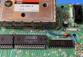
Fig. 9 - The completed modification on the component side.


