LaserActive:CLD-A100 Power Supply Testing: Difference between revisions
No edit summary |
m (Zaxour moved page LaserActive:CLD-A100 Power Supply Testing to LaserActive:CLD-A100 Power Supply Testing) |
Revision as of 14:41, 6 July 2022
The Nichicon power supply in the Pioneer Laseractive CLD-A100 will not produce all of it's DC voltage outputs by simply plugging it into the mains. It requires that the power switch be engaged and that it receives a "POWER ON" signal from the Interface (INTF) board. However, if it is desired to test the power supply for troubleshooting or after servicing, there are two locations to short circuit in order to get the power supply into a so-called "Bench Test" mode.
Power Supply Bench Test Mode
First, short the two pins of CN002 (power switch connector), which will allow the AC-DC converter circuitry on the primary side to operate. This will allow the "EVER +5V" rail to come up.
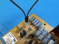
Using a jumper wire to short CN002

Next, short pins 5 and 6 of CN4 together either via solder bridge, or use a cut component leg to place in the connector socket itself. This ties the "EVER +5V" voltage rail to the "POWER ON" signal line, allowing the power supply to bring up the "SW" +5V, -5V, +14V and - 14V rails.
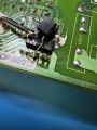
Using a solder bridge to short pins 5-6 on CN4

It is now possible to measure all of the voltages on the power supply.
Measuring Power Supply Voltages
When measuring voltages on the power supply, either measure at the connectors directly, or on the side of the circuit protection element (ICP) that is electrically connected to the connector. The ICP's to measure are IC101, IC102, IC201, IC202 and IC301. Additionally, as shown in the image demonstrating shorting pins on CN4, some power supplies will already have an additional ICP-N50 element added on the bottom, denoated as "IC204." Ensure that BOTH legs of all these ICP's are within tolerance of the nominal voltage levels (+/-5-5.3V for the +/- 5V rails, +/- 13.5-14.5 for the +/- 14V rails).
When finished, remember to remove the jumpers/solder bridges and ensure that the connector pin solder joints are adequate.