LaserActive:PSU ICP Mod: Difference between revisions
| Line 5: | Line 5: | ||
===Sever Existing +5V Trace to CN4=== | ===Sever Existing +5V Trace to CN4=== | ||
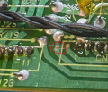
Using a hobby knife, sever the trace as indicated in the photo. For clarity, the trace is just to the left of the silkscreen box enclosing the pins for CN1. | Using a hobby knife, sever the trace as indicated in the photo. For clarity, the trace is just to the left of the silkscreen box enclosing the pins for CN1. | ||
Do not remove RJ25, as it is used to bias the +5V rail (pin 1) on CN1. | |||
<gallery> | <gallery> | ||
CLDA100 PSU CutTrace.png|+5V Trace to INTF Severed for ICP-N50 Installation | CLDA100 PSU CutTrace.png|+5V Trace to INTF Severed for ICP-N50 Installation | ||
Revision as of 19:02, 1 August 2022
With later revisions of the CLD-A100 power supply, Pioneer/Nichicon began to install an additional ICP-N50 circuit protection element for the +5V rail supplying the INTF board.
Installation Guide
Sever Existing +5V Trace to CN4
Using a hobby knife, sever the trace as indicated in the photo. For clarity, the trace is just to the left of the silkscreen box enclosing the pins for CN1.
Do not remove RJ25, as it is used to bias the +5V rail (pin 1) on CN1.
+5V Trace to INTF Severed for ICP-N50 Installation

Install ICP-N50
Apply insulating material, such as polyimide/kapton tape around the area where the new ICP will lay. Lead form one leg of the ICP to face towards IC202. Using 24AWG+ diameter wire, solder the leg facing IC202 to the "upper" leg of IC202 (the leg further from CN3). The other leg of the ICP should be facing CN1. Solder the leg to CN4, pins 3 and 4. The leg can be placed between the two pins for ease of installation.
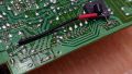
Additional ICP-N50 Installed
