GBA:Innovation GBA TV Converter Direct-Solder Installation Guide: Difference between revisions
Jump to navigation
Jump to search
Black Majic (talk | contribs) m (Black Majic moved page RetroRGB Migration:Innovation GBA TV Converter Direct-Solder Installation Guide to GBA:Innovation GBA TV Converter Direct-Solder Installation Guide: Proper title for page) |
m (Derf moved page GBA:Innovation GBA TV Converter Direct-Solder Installation Guide to GBA:Innovation GBA TV Converter Direct-Solder Installation Guide) |
||
| (3 intermediate revisions by 2 users not shown) | |||
| Line 1: | Line 1: | ||
{{Warning|This is an extremely difficult and destructive mod. Be warned, once you start this process, there's no going back, as you'll be cutting the ribbon cable!}} | |||
This page describes a mod to the [[RetroRGB_Migration:Innovation GBA TV Converter]] by directly soldering to the video pins of your Game Boy Advance. This will bypass the original ribbon installation that produces horrible picture quality. | |||
This page describes a mod to the [[ | |||
Once the converter is installed, [[RetroRGB_Migration:Innovation GBA TV Converter RGB Guide|you can mod it for RGB]]. | |||
== Installation == | == Installation == | ||
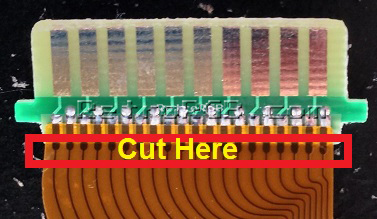
# First, cut the ribbon cable right where it meets the main connector: <br>[[File:GBAPage09.JPG]] | # First, cut the ribbon cable right where it meets the main connector:<br>[[File:GBAPage09.JPG]] | ||
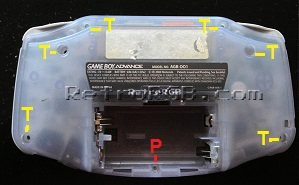
# Remove the back cover from the GBA ('T' is for tri-wing screws, 'P' for Philips head): <br>[[File:GBAPage10.jpg]] | # Remove the back cover from the GBA ('T' is for tri-wing screws, 'P' for Philips head):<br>[[File:GBAPage10.jpg]] | ||
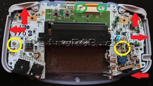
# Remove all the plastic pieces, simply by pulling them out (red arrows). | # Remove all the plastic pieces, simply by pulling them out (red arrows). Then, remove the two Philips head screws holding the board in (yellow circles), as well as the ribbon cable. Loosen the two points on either side of the cable to get it to pop out (green circles):<br>[[File:GBAPage11.jpg]] | ||
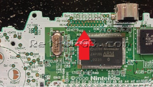
# Flip the board over and locate the following section | # Flip the board over and locate the following section. It will be slightly different looking in different versions of the GBA, but all pins and locations are the same:<br>[[File:GBAPage12.jpg]] | ||
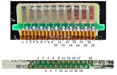
# Solder the following pins from the GBA to the ribbon cable connector, matching the numbers exactly as in this diagram: <br>[[File:GBAPage13.jpg]] | # Solder the following pins from the GBA to the ribbon cable connector, matching the numbers exactly as in this diagram: <br>[[File:GBAPage13.jpg]] | ||
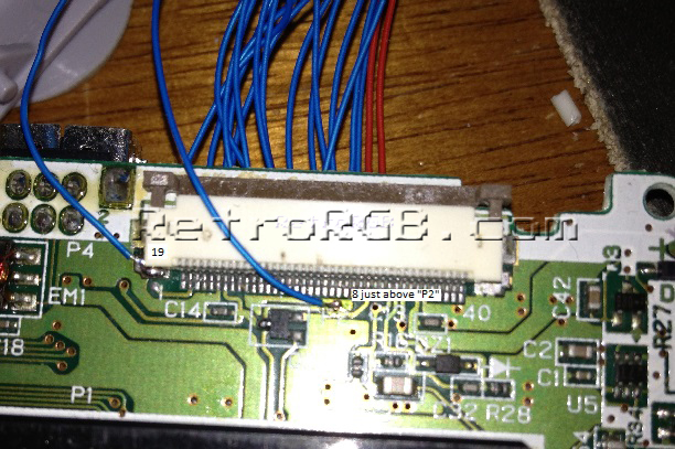
# Flip it over for the final two pins (8 and 19): <br>[[File:GBAPage14.jpg]] | # Flip it over for the final two pins (8 and 19): <br>[[File:GBAPage14.jpg]] | ||
| Line 16: | Line 14: | ||
# Re-assemble everything and be sure when you put the connector into the new rear cover (provided with the kit) that the side you soldered the cable to is facing the inside of the GBA, not away from it! | # Re-assemble everything and be sure when you put the connector into the new rear cover (provided with the kit) that the side you soldered the cable to is facing the inside of the GBA, not away from it! | ||
# Attach the new back cover to your GBA, and test it out. If it no longer works, something went wrong and you'll need to go back and troubleshoot. Look for damage, or solder bridges. If everything went well, hook up the TV attachment and plug it into a regular composite (or S-Video) input and make sure the installation worked. | # Attach the new back cover to your GBA, and test it out. If it no longer works, something went wrong and you'll need to go back and troubleshoot. Look for damage, or solder bridges. If everything went well, hook up the TV attachment and plug it into a regular composite (or S-Video) input and make sure the installation worked. | ||
Latest revision as of 04:20, 5 July 2022
| This is an extremely difficult and destructive mod. Be warned, once you start this process, there's no going back, as you'll be cutting the ribbon cable! |
This page describes a mod to the GBA:Innovation GBA TV Converter by directly soldering to the video pins of your Game Boy Advance. This will bypass the original ribbon installation that produces horrible picture quality.
Once the converter is installed, you can mod it for RGB.
Installation
- First, cut the ribbon cable right where it meets the main connector:
- Remove the back cover from the GBA ('T' is for tri-wing screws, 'P' for Philips head):
- Remove all the plastic pieces, simply by pulling them out (red arrows). Then, remove the two Philips head screws holding the board in (yellow circles), as well as the ribbon cable. Loosen the two points on either side of the cable to get it to pop out (green circles):
- Flip the board over and locate the following section. It will be slightly different looking in different versions of the GBA, but all pins and locations are the same:
- Solder the following pins from the GBA to the ribbon cable connector, matching the numbers exactly as in this diagram:
- Flip it over for the final two pins (8 and 19):
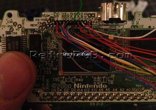
- Your GBA should look something like this now:
- Re-assemble everything and be sure when you put the connector into the new rear cover (provided with the kit) that the side you soldered the cable to is facing the inside of the GBA, not away from it!
- Attach the new back cover to your GBA, and test it out. If it no longer works, something went wrong and you'll need to go back and troubleshoot. Look for damage, or solder bridges. If everything went well, hook up the TV attachment and plug it into a regular composite (or S-Video) input and make sure the installation worked.


