Intellivision:Yannick RGB Mod: Difference between revisions
(Created page with " == Version 2 Correction == In some cases after installing the Yannick RGB mod, you may see that a top portion of the screen is misaligned or "flagging" as shown in the image below. : 300px If this is the case with your install, you can fix this by cutting a trace and bridging one side of the trace to ground on the bottom of the RGB board as described below. # Cut the trace marked with red on the bottom side: <br> File:Yan...") |
No edit summary |
||
| Line 1: | Line 1: | ||
One option for RGB output on an Intellivision is to use the Yannick RGB board. Note that you will need to either cut a hole in the case or remove the RF port completely to be able to access the video port you wish to install. Audio output is also mono, so you may wish to bridge two pins of the output jack or to add extra RCA jacks to be able to send audio to two speakers. | |||
Ivory Tower Collections created a [[File:Intellivision Yannick RGB Installation.pdf|great installation guide]] as well as a [https://www.youtube.com/watch?v=gl8_gI-COuM video demonstrating the installation of the RGB board]. | |||
== Version 2 Correction == | == Version 2 Correction == | ||
Revision as of 03:45, 13 December 2022
One option for RGB output on an Intellivision is to use the Yannick RGB board. Note that you will need to either cut a hole in the case or remove the RF port completely to be able to access the video port you wish to install. Audio output is also mono, so you may wish to bridge two pins of the output jack or to add extra RCA jacks to be able to send audio to two speakers.
Ivory Tower Collections created a File:Intellivision Yannick RGB Installation.pdf as well as a video demonstrating the installation of the RGB board.
Version 2 Correction
In some cases after installing the Yannick RGB mod, you may see that a top portion of the screen is misaligned or "flagging" as shown in the image below.

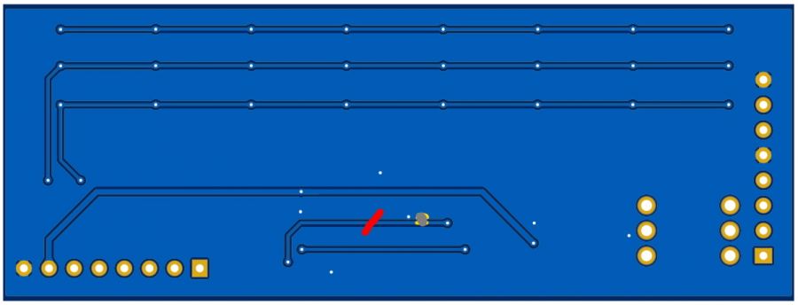
If this is the case with your install, you can fix this by cutting a trace and bridging one side of the trace to ground on the bottom of the RGB board as described below.
- Cut the trace marked with red on the bottom side:
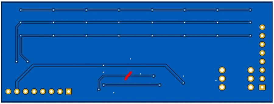
- Scratch the solder mask to reveal copper on both the trace and the ground plane:
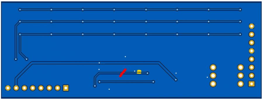
- Put a solder blob across the trace and ground plane to connect them: