Xbox 360:RGH/RGH1.2: Difference between revisions
Jump to navigation
Jump to search
(Formatting) |
(Added images and updated some of them) |
||
| Line 20: | Line 20: | ||
**[[Xbox 360:JR Programmer|JR-Programmer]] | **[[Xbox 360:JR Programmer|JR-Programmer]] | ||
**[[Xbox 360:Matrix Programmer|Modified Matrix Flasher]] | **[[Xbox 360:Matrix Programmer|Modified Matrix Flasher]] | ||
*[[Xbox 360:Standard NAND|NAND | *NAND Backup with XeLL written to the console | ||
**[[Xbox 360:Standard NAND|Standard NAND]] | |||
**[[Xbox 360:4GB NAND|4GB Corona]] | |||
* [https://github.com/Octal450/J-Runner-with-Extras/releases/latest J-Runner with Extras] (Includes RGH1.2 V2 Matrix/Coolrunner Timings) | * [https://github.com/Octal450/J-Runner-with-Extras/releases/latest J-Runner with Extras] (Includes RGH1.2 V2 Matrix/Coolrunner Timings) | ||
*[https://github.com/Octal450/Timing-Files/releases/download/Timings/RGH1.2-V2.rar RGH1.2 V2 Timing Files] (X360ACE/Squirt chips only) | *[https://github.com/Octal450/Timing-Files/releases/download/Timings/RGH1.2-V2.rar RGH1.2 V2 Timing Files] (X360ACE/Squirt chips only) | ||
| Line 27: | Line 29: | ||
===Motherboard points=== | ===Motherboard points=== | ||
[[File:Phat360PLLFix.jpg|thumb|400x400px|PLL Repair on a Phat motherboard (required if bottom pad is damaged)]] | |||
====Phat (Non-Xenon)==== | ====Phat (Non-Xenon)==== | ||
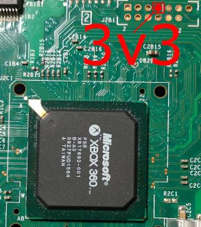
*[[ | * 3.3v [[File:Y5p0dxP.jpg|331x331px]] | ||
* | *1.8V '''(Only if using an X360 ACE)''' [[File:1v8-HDMI.png|frameless]] | ||
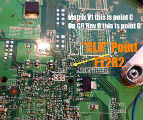
*PLL | *PLL | ||
**[[ | ** Bottom [[File:Fat360PLL.jpg|frameless|290x290px]] | ||
** | **Top (under CPU heatsink; requires scraping) [[File:Fat360topPLL.jpg|frameless|288x288px]] | ||
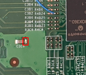
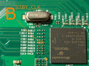
*STBY_CLK | *STBY_CLK | ||
**[[ | **Bottom [[File:CLK.png|frameless|287x287px]] | ||
** | **Top (There are 2 points boxed; either can be used.) [[File:Fat360STBY CLK.jpg|frameless|286x286px]] | ||
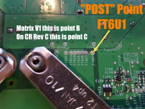
*POST | *POST | ||
**[[ | **Bottom [[File:Post.png|frameless|287x287px]] | ||
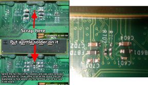
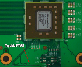
** | **Top (requires scraping) [[File:FT6U1 topside.png|frameless|285x285px]] | ||
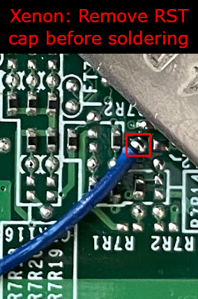
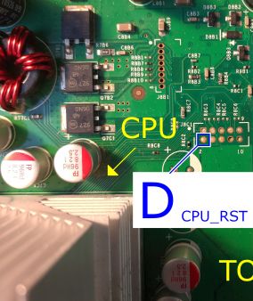
* CPU_RST | *CPU_RST | ||
**[[ | **R8C2 (Performs better) [[File:VXi9LgC.jpg|frameless|311x311px]] | ||
**[[ | **C7R112 [[File:RST.png|frameless]] | ||
**[[ | **J8C1: (Easier to solder) [[File:Cp2OBF3.jpeg|frameless|338x338px]] | ||
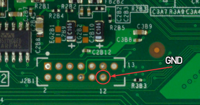
*GND | *GND | ||
**[ | **Near 3.3v [[File:J2b1gnd.png|frameless|282x282px]] | ||
**AV Port | **AV Port | ||
**Any other ground point[[File:5lY3TID.png|thumb]] | |||
====Slim (Trinity)==== | ====Slim (Trinity)==== | ||
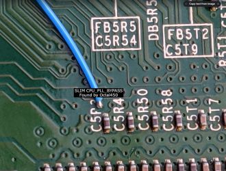
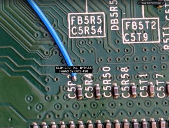
*[[:File:RGH1.2 Slim PLL.jpg|PLL]] | *[[:File:RGH1.2 Slim PLL.jpg|PLL]][[File:RGH1.2 Slim PLL.jpg|frameless|330x330px]] | ||
**No alternative point! | **No alternative point! | ||
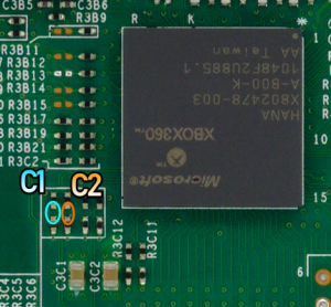
*CPU_CLK '''(Only if using an X360 ACE V4/V5)''' | * CPU_CLK '''(Only if using an X360 ACE V4/V5)''' | ||
**[ | **Top [[File:TrinityC1C2.png|frameless]] | ||
***There are two points circled for C1 and C2 respectively; either can be used | ***There are two points circled for C1 and C2 respectively; either can be used or bridged. | ||
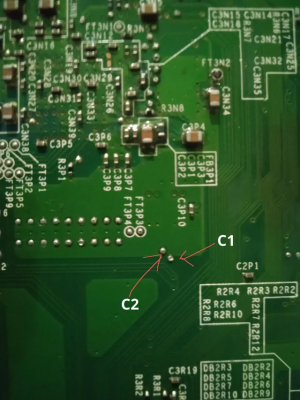
**[ | **Bottom [[File:TrinityBottomC1C2.png|frameless]] | ||
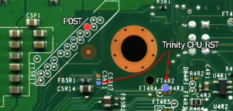
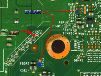
*[ | *POST & RST [[File:TrinityPOSTandRST.png|frameless|328x328px]] | ||
** | **There are two RST points, either can be used. | ||
**A Postfix adapter can be used on Trinity in case it's damaged | **A Postfix adapter can be used on Trinity in case it's damaged. | ||
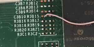
*STBY_CLK | *STBY_CLK | ||
**[ | **C3B10 (Top) [[File:TrinityHanaCLK.jpg|frameless]] | ||
** [ | **FT3N2 (Bottom) [[File:Ft3n2.jpg|frameless|301x301px]] | ||
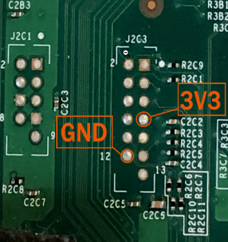
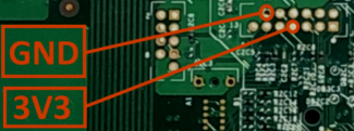
* | *GND & 3.3V [[File:Trinity 3v3GND.png|frameless|350x350px]] | ||
====Slim (Corona)==== | ==== Slim (Corona)==== | ||
*[[:File:RGH1.2 Slim PLL.jpg|PLL]] | *[[:File:RGH1.2 Slim PLL.jpg|PLL]][[File:RGH1.2 Slim PLL.jpg|frameless|329x329px]] | ||
**No alternative point! | **No alternative point! | ||
* | *CPU_CLK '''(Only if using an X360 ACE V4/V5)''' [[File:CoronaCPUCLK.png|frameless|328x328px]] | ||
**There are two points circled for C1 and C2 respectively; either can be used | **There are two points circled for C1 and C2 respectively; either can be used or bridged. | ||
*[ | * POST & RST [[File:Corona POSTandRST.png|frameless|327x327px]] | ||
**If POST on the bottom is disabled (like in Waitsburg & Stingray boards) or damaged, a postfix adapter is required. [[ | **There are two RST points, either can be used. | ||
**If POST on the bottom is disabled (like in Waitsburg & Stingray boards) or damaged, a postfix adapter is required. | |||
*GND & 3.3V [[File:Corona 3v3GND.png|frameless|325x325px]] | |||
=== Glitch chip pinouts & diagrams === | === Glitch chip pinouts & diagrams=== | ||
====Phat==== | ====Phat==== | ||
=====[[:File:Coolrunnerrevcrgh12.jpg|Coolrunner Rev A/B/C/D]] ===== | =====[[:File:Coolrunnerrevcrgh12.jpg|Coolrunner Rev A/B/C/D]] ===== | ||
*A - PLL | *A - PLL | ||
*B - STBY_CLK (only if not using oscillator) | *B - STBY_CLK (only if not using oscillator) | ||
| Line 83: | Line 87: | ||
*D - RST | *D - RST | ||
===== [[:File:Cr3litergh12.jpg|CR3 Lite]] ===== | =====[[:File:Cr3litergh12.jpg|CR3 Lite]]===== | ||
*A - PLL | *A - PLL | ||
*B - STBY_CLK (only if not using oscillator) | *B - STBY_CLK (only if not using oscillator) | ||
*C - POST | *C - POST | ||
*D - RST | *D - RST | ||
=====[[:File:Matrixglitcherrgh12diagram.jpg|Matrix Glitcher]]===== | ===== [[:File:Matrixglitcherrgh12diagram.jpg|Matrix Glitcher]]===== | ||
*A - RST | *A - RST | ||
*B - POST | *B - POST | ||
| Line 100: | Line 104: | ||
*Pinout follows written labels | *Pinout follows written labels | ||
*Don't use POST or RST tuners | *Don't use POST or RST tuners | ||
[[File:1v8-X360ACE.jpg|thumb|1.8v on an Ace V3]] | |||
=====[[:File:X360acergh12phatinstalldiagram.png|X360ACE (V1/V2/V3), DGX]]===== | =====[[:File:X360acergh12phatinstalldiagram.png|X360ACE (V1/V2/V3), DGX]]===== | ||
| Line 106: | Line 111: | ||
*E - STBY_CLK (only if not using oscillator version) | *E - STBY_CLK (only if not using oscillator version) | ||
*F - PLL (22K ohm resistor required) | *F - PLL (22K ohm resistor required) | ||
* | *Remember to remove the diode and connect 1.8V | ||
====Slim==== | ====Slim ==== | ||
=====Coolrunner Rev A/B/C/D===== | =====Coolrunner Rev A/B/C/D===== | ||
| Line 120: | Line 125: | ||
*C - POST | *C - POST | ||
*D - RST | *D - RST | ||
* E - PLL (10K ohm resistor recommended) | *E - PLL (10K ohm resistor recommended) | ||
=====[[:File:RGH1.2_Corona_Diagram.jpg|Matrix Glitcher (Corona)]] ===== | =====[[:File:RGH1.2_Corona_Diagram.jpg|Matrix Glitcher (Corona)]]===== | ||
*A - RST | *A - RST | ||
*B - POST | *B - POST | ||
*E - PLL (10K ohm resistor recommended) | *E - PLL (10K ohm resistor recommended) | ||
===== [[:File:RGH1.2_Trinity_Diagram.jpg|Matrix Glitcher (Trinity)]]===== | =====[[:File:RGH1.2_Trinity_Diagram.jpg|Matrix Glitcher (Trinity)]]===== | ||
*A - RST | *A - RST | ||
*B - POST | *B - POST | ||
| Line 135: | Line 140: | ||
=====X360ACE (V1/V2/V3/V3+), DGX===== | =====X360ACE (V1/V2/V3/V3+), DGX===== | ||
*C - POST | *C - POST | ||
*D - RST | * D - RST | ||
* F - PLL (10K ohm resistor recommended) | *F - PLL (10K ohm resistor recommended) | ||
=====X360ACE V4/V5===== | =====X360ACE V4/V5===== | ||
*A - RST | *A - RST | ||
*B - POST | * B - POST | ||
* C1 - CPU_CLK_DP | *C1 - CPU_CLK_DP | ||
*C2 - CPU_CLK_DN | *C2 - CPU_CLK_DN | ||
*D - PLL (10K ohm resistor required) | *D - PLL (10K ohm resistor required) | ||
| Line 151: | Line 156: | ||
*Don't use POST or RST tuners | *Don't use POST or RST tuners | ||
==Programming the Glitch Chip == | ==Programming the Glitch Chip== | ||
#Plug the cable from your programmer into the chip programmer. | #Plug the cable from your programmer into the chip programmer. | ||
#*If you are using an xFlasher, ensure the switch is set to <code>SPI</code>. | #*If you are using an xFlasher, ensure the switch is set to <code>SPI</code>. | ||
#* CoolRunner: Slide switch to "PRG". | #*CoolRunner: Slide switch to "PRG". | ||
#Open J-Runner with Extras. Click "Program Timing File" in the upper left and select your console’s tab and the relevant radio button for RGH 1.2. | #Open J-Runner with Extras. Click "Program Timing File" in the upper left and select your console’s tab and the relevant radio button for RGH 1.2. | ||
#Click "Program". When complete, unplug the cable from the glitch chip. | #Click "Program". When complete, unplug the cable from the glitch chip. | ||
| Line 166: | Line 171: | ||
==Decrypting the NAND== | ==Decrypting the NAND== | ||
#Connect Ethernet and power on the console. The glitch chip should blink once or more times, and then the console should start into XeLL RELOADED. | # Connect Ethernet and power on the console. The glitch chip should blink once or more times, and then the console should start into XeLL RELOADED. | ||
#Once XeLL finishes, it will display your CPU key and some other info. There is also an IP address. | #Once XeLL finishes, it will display your CPU key and some other info. There is also an IP address. | ||
#Enter the IP address into the box on the lower right of J-Runner and click "Get CPU Key". J-Runner will pull the info from the box, and decrypt the NANDs automatically. | #Enter the IP address into the box on the lower right of J-Runner and click "Get CPU Key". J-Runner will pull the info from the box, and decrypt the NANDs automatically. | ||
| Line 172: | Line 177: | ||
==Writing New NAND Image== | ==Writing New NAND Image== | ||
#Power down the console, and connect your programmer to the motherboard. | # Power down the console, and connect your programmer to the motherboard. | ||
#*If you are using an xFlasher, ensure the switch is set to <code>SPI</code>. | #*If you are using an xFlasher, ensure the switch is set to <code>SPI</code>. | ||
#In the upper right of J-Runner, ensure the <code>Glitch2</code> radio button is selected. | #In the upper right of J-Runner, ensure the <code>Glitch2</code> radio button is selected. | ||
#*Make sure <code>SMC+</code> is enabled for better boot times. | #* Make sure <code>SMC+</code> is enabled for better boot times. | ||
# Click "Create XeBuild Image". This will take a few moments. | #Click "Create XeBuild Image". This will take a few moments. | ||
#Click "Write NAND". | #Click "Write NAND". | ||
#Disconnect your programmer when the process completes. | #Disconnect your programmer when the process completes. | ||
#Boot the console several times and ensure it boots consistently. If not, make sure your wiring is clean and neat and avoids noisy area. Run the wires near the X-Clamps for best results. | #Boot the console several times and ensure it boots consistently. If not, make sure your wiring is clean and neat and avoids noisy area. Run the wires near the X-Clamps for best results. | ||
#Return to the RGH main page and continue in the [[Xbox_360:RGH#Cleaning_Up|Cleaning Up section]]. | #Return to the RGH main page and continue in the [[Xbox_360:RGH#Cleaning_Up|Cleaning Up section]]. | ||
Revision as of 12:26, 13 August 2023
RGH1.2 combines RGH1-like PLL slowdown with Glitch2 images to allow reliable glitching of Falcon/Jasper consoles with split CB (post 14699 kernel). RGH1.2 V2 ports this hack to Trinity/Corona consoles as well as fixing a few issues on Jaspers.
Equipment Needed
- A glitch chip:
- Coolrunner Rev A/B/C/D
- CR3 Lite
- Matrix Glitcher
- Squirt BGA/Reloaded
- X360ACE V1/V2/V3
- X360ACE V3+/V4/V5 (Trinity/Corona only)
- DGX
- A PC running Windows Vista or later
- A soldering iron, solder, and flux (MG 835 recommended)
- Isopropyl alcohol (91% or higher recommended) and cotton swabs
- A NAND and glitch chip programmer:
- NAND Backup with XeLL written to the console
- J-Runner with Extras (Includes RGH1.2 V2 Matrix/Coolrunner Timings)
- RGH1.2 V2 Timing Files (X360ACE/Squirt chips only)
Glitch Chip Installation
Motherboard points

Phat (Non-Xenon)
- 3.3v
- 1.8V (Only if using an X360 ACE)
- PLL
- Bottom
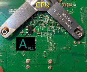
- Top (under CPU heatsink; requires scraping)
- Bottom
- STBY_CLK
- Bottom
- Top (There are 2 points boxed; either can be used.)
- Bottom
- POST
- Bottom
- Top (requires scraping)
- Bottom
- CPU_RST
- R8C2 (Performs better)
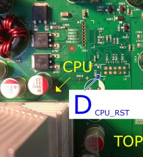
- C7R112
- J8C1: (Easier to solder)
- R8C2 (Performs better)
- GND
- Near 3.3v
- AV Port
- Any other ground point
- Near 3.3v


Slim (Trinity)
- PLL
- No alternative point!
- CPU_CLK (Only if using an X360 ACE V4/V5)
- Top
- There are two points circled for C1 and C2 respectively; either can be used or bridged.
- Bottom
- Top
- POST & RST
- There are two RST points, either can be used.
- A Postfix adapter can be used on Trinity in case it's damaged.
- STBY_CLK
- C3B10 (Top)
- FT3N2 (Bottom)
- C3B10 (Top)
- GND & 3.3V


Slim (Corona)
- PLL
- No alternative point!
- CPU_CLK (Only if using an X360 ACE V4/V5)
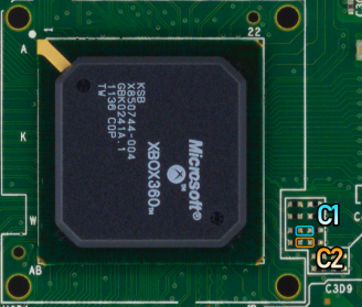
- There are two points circled for C1 and C2 respectively; either can be used or bridged.
- POST & RST
- There are two RST points, either can be used.
- If POST on the bottom is disabled (like in Waitsburg & Stingray boards) or damaged, a postfix adapter is required.
- GND & 3.3V


Glitch chip pinouts & diagrams
Phat
Coolrunner Rev A/B/C/D
- A - PLL
- B - STBY_CLK (only if not using oscillator)
- C - POST
- D - RST
CR3 Lite
- A - PLL
- B - STBY_CLK (only if not using oscillator)
- C - POST
- D - RST
Matrix Glitcher
- A - RST
- B - POST
- C - STBY_CLK (only if not using oscillator)
- F - PLL
Squirt
- Squirt BGA 1.2: Disable the onboard 670pf and/or 480pf caps by removing R7 and R8
- Squirt Reloaded 2.X: remove R2 and connect STBY_CLK
- Pinout follows written labels
- Don't use POST or RST tuners

X360ACE (V1/V2/V3), DGX
- C - POST
- D - RST
- E - STBY_CLK (only if not using oscillator version)
- F - PLL (22K ohm resistor required)
- Remember to remove the diode and connect 1.8V
Slim
Coolrunner Rev A/B/C/D
- B - STBY_CLK (only if not using oscillator)
- C - POST
- D - RST
- E - PLL (10K ohm resistor recommended)
CR3 Lite
- B - STBY_CLK (only if not using oscillator)
- C - POST
- D - RST
- E - PLL (10K ohm resistor recommended)
Matrix Glitcher (Corona)
- A - RST
- B - POST
- E - PLL (10K ohm resistor recommended)
Matrix Glitcher (Trinity)
- A - RST
- B - POST
- C - STBY_CLK (only if not using oscillator)
- E - PLL (10K ohm resistor recommended)
X360ACE (V1/V2/V3/V3+), DGX
- C - POST
- D - RST
- F - PLL (10K ohm resistor recommended)
X360ACE V4/V5
- A - RST
- B - POST
- C1 - CPU_CLK_DP
- C2 - CPU_CLK_DN
- D - PLL (10K ohm resistor required)
Squirt
- Squirt Reloaded 2.X: remove R2 and connect STBY_CLK or remove 100 MHz and add 48 MHz oscillator
- Use SCL pad for PLL
- Pinout follows written labels
- Don't use POST or RST tuners
Programming the Glitch Chip
- Plug the cable from your programmer into the chip programmer.
- If you are using an xFlasher, ensure the switch is set to
SPI. - CoolRunner: Slide switch to "PRG".
- If you are using an xFlasher, ensure the switch is set to
- Open J-Runner with Extras. Click "Program Timing File" in the upper left and select your console’s tab and the relevant radio button for RGH 1.2.
- Click "Program". When complete, unplug the cable from the glitch chip.
- Coolrunner: Set the switch back to "NOR".
X360ACE V4/V5/V3+
- xFlasher or other Gowin compatible programmer required in order to program these chips
- Programming Instructions
Decrypting the NAND
- Connect Ethernet and power on the console. The glitch chip should blink once or more times, and then the console should start into XeLL RELOADED.
- Once XeLL finishes, it will display your CPU key and some other info. There is also an IP address.
- Enter the IP address into the box on the lower right of J-Runner and click "Get CPU Key". J-Runner will pull the info from the box, and decrypt the NANDs automatically.
Writing New NAND Image
- Power down the console, and connect your programmer to the motherboard.
- If you are using an xFlasher, ensure the switch is set to
SPI.
- If you are using an xFlasher, ensure the switch is set to
- In the upper right of J-Runner, ensure the
Glitch2radio button is selected.- Make sure
SMC+is enabled for better boot times.
- Make sure
- Click "Create XeBuild Image". This will take a few moments.
- Click "Write NAND".
- Disconnect your programmer when the process completes.
- Boot the console several times and ensure it boots consistently. If not, make sure your wiring is clean and neat and avoids noisy area. Run the wires near the X-Clamps for best results.
- Return to the RGH main page and continue in the Cleaning Up section.