Xbox 360:RGH/RGH1.2: Difference between revisions
m (Corrected CoolRunner PLL pad from E to A) |
No edit summary |
||
| (11 intermediate revisions by 2 users not shown) | |||
| Line 1: | Line 1: | ||
[[Category: | [[Category:Xbox 360]] | ||
{{Warning|The steps on this page are considered risky for your console, as there is a chance you can brick it. Please have someone else mod your console if you are not experienced in soldering!}} | {{Warning|The steps on this page are considered risky for your console, as there is a chance you can brick it. Please have someone else mod your console if you are not experienced in soldering!}} | ||
RGH1.2 combines RGH1-like PLL slowdown with Glitch2 images to allow reliable glitching of Falcon/Jasper consoles with split CB (post 14699 kernel). RGH1.2 V2 ports this hack to Trinity/Corona consoles as well as fixing a few issues on Jaspers. | RGH1.2 combines RGH1-like PLL slowdown with Glitch2 images to allow reliable glitching of Falcon/Jasper consoles with split CB (post 14699 kernel). RGH1.2 V2 ports this hack to Trinity/Corona consoles as well as fixing a few issues on Jaspers. | ||
| Line 34: | Line 34: | ||
{{Xbox 360 NAND Flashers}} | {{Xbox 360 NAND Flashers}} | ||
== Programming the Glitch Chip == | == Programming the Glitch Chip == | ||
=== Standard Xilinx-based Glitch Chip === | |||
This includes common chips like the CoolRunner, Matrix V1/V3, X360ACE V1/V2/V3, etc. | |||
#Plug the cable from your programmer into the chip programmer. | #Plug the cable from your programmer into the chip programmer. | ||
#*If you are using an xFlasher, ensure the switch is set to <code>SPI</code>. | #*If you are using an xFlasher, ensure the switch is set to <code>SPI</code>. | ||
| Line 42: | Line 45: | ||
#*Coolrunner: Set the switch back to "NOR". | #*Coolrunner: Set the switch back to "NOR". | ||
=== X360ACE V3+/V4/V5 === | |||
xFlasher 360 or other Gowin compatible programmer is required in order to program these chips. | |||
== | ==== [[Xbox_360:Programming_Gowin-based_X360ACE_Chips|Programming Instructions]] ==== | ||
On Waitsburg and Stingray | |||
==Corona Specific Instructions== | |||
On later revisions of Corona based motherboards (named Waitsburg and Stingray for Xbox 360 S and E respectively), the trace connecting the CPU's POST to the POST pad on the bottom of the motherboard has been removed, so you need to use a postfix adapter to be able to attach a pogo pin to the POST connection underneath the CPU, allowing for CPU POST output once again. You can use the following image to determine if you need the adapter or not by removing the heatsink: | |||
[[File:Corona POST.png]] | [[File:Corona POST.png]] | ||
You can also identify if you have a Waitsburg motherboard instead of a Corona by looking for the part number of | You can also identify if you have a Waitsburg motherboard instead of a Corona by looking for the part number of <code>X862605</code> on the bottom left of the PCB. Generally, Xbox 360 S consoles manufactured in 2012 will be Waitsburgs and need postfix adapters for RGH. Every Stingray will also need a postfix adapter with RGH. | ||
As shown in following diagram, you can install it by carefully sliding the larger piece of the adapter onto the left side of the CPU (when looking at the CPU from a readable position). Gently press the PCB inward toward the CPU to depress the pogo pin, and slide the smaller PCB part over the other side of the CPU, interlocking the two PCBs together. Solder the four anchor points on the edges of the postfix adapter to prevent it from coming loose. | As shown in following diagram, you can install it by carefully sliding the larger piece of the adapter onto the left side of the CPU (when looking at the CPU from a readable position). Gently press the PCB inward toward the CPU to depress the pogo pin, and slide the smaller PCB part over the other side of the CPU, interlocking the two PCBs together. Solder the four anchor points on the edges of the postfix adapter to prevent it from coming loose. | ||
[[File:Full Postfix Guide.png]] | [[File:Full Postfix Guide.png|2015x2015px]] | ||
==Glitch Chip Installation== | ==Glitch Chip Installation== | ||
===Motherboard Points=== | ===Motherboard Points=== | ||
====[[Xbox 360:RGH/Solder Points# | ====Phat==== | ||
==== [[ | |||
=== Glitch Chip Pinouts === | =====3.3v, 5v, and GND===== | ||
*J2B1 | |||
**[[File:J2B1.png|500x500px]] | |||
=====1.8V '''(Only if using an X360 ACE V1/V2/V3)'''===== | |||
*'''Non-Xenon''' | |||
**[[File:1v8-HDMI.png|frameless]] | |||
* '''Xenon''' | |||
**[[File:1v8-Xenon.png|frameless]] | |||
[[File:Phat360PLLFix.jpg|thumb|400x400px|PLL Repair on a Phat motherboard (required if bottom pad is damaged). Image credit to TheLazyITGuy.]] | |||
=====CPU_RST===== | |||
*C7R112 | |||
**[[File:RST.png|frameless]] | |||
*R8C2 | |||
** [[File:VXi9LgC.jpg|frameless|311x311px]] | |||
*J8C1 | |||
**'''Not recommended.''' | |||
**[[File:Cp2OBF3.jpeg|frameless|338x338px]] | |||
===== FT6U1 POST ===== | |||
*Bottom | |||
**[[File:Post.png|frameless|287x287px]] | |||
*Top (requires scraping) | |||
**[[File:FT6U1 topside.png|frameless|285x285px]] | |||
===== GND ===== | |||
*[[Xbox 360:RGH/Solder Points#3.3v, GND, and RGH 2 i2C|J2B1 Header]] | |||
*AV Port | |||
*'''Any other ground point''' | |||
===== PLL ===== | |||
*Bottom | |||
**[[File:Fat360PLL.jpg|frameless|290x290px]] | |||
*Top (under CPU heatsink; requires scraping) | |||
** [[File:Fat360topPLL.jpg|frameless|288x288px]] | |||
===== STBY_CLK ===== | |||
*Top (Xenon) | |||
**[[File:STBY_CLK-Xenon.png]] | |||
*Top '''(Non-Xenon)''' | |||
**[[File:Fat360STBY CLK.jpg|frameless|286x286px]] | |||
**There are 2 points boxed; either can be used. | |||
*Bottom '''(Non-Xenon)''' | |||
**[[File:CLK.png|frameless|287x287px]] | |||
==== Trinity==== | |||
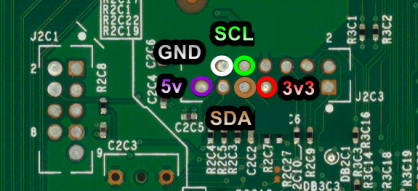
=====3.3v, 5v, and GND===== | |||
*J2C3 | |||
**[[File:J2C3Trinity.png|frameless|391x391px]] | |||
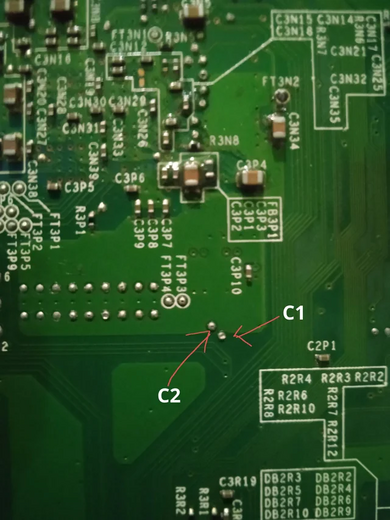
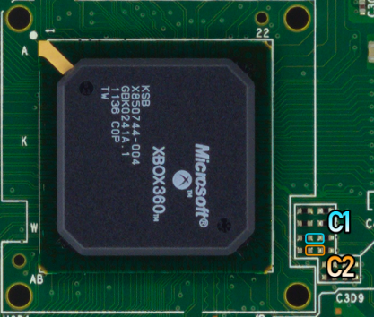
=====CPU_CLK '''(Only if using an X360 ACE V4/V5)'''===== | |||
*Top (HANA) | |||
**[[File:TrinityC1C2.png|frameless|390x390px]] | |||
**There are two points circled for C1 and C2 respectively; either can be used or bridged. | |||
*Bottom | |||
** [[File:TrinityBottomC1C2.png|frameless|520x520px]] | |||
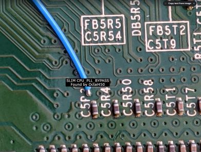
=====PLL===== | |||
* Bottom (Requires scraping) | |||
**[[File:RGH1.2 Slim PLL.jpg|frameless|391x391px]] | |||
**'''No alternative point!''' | |||
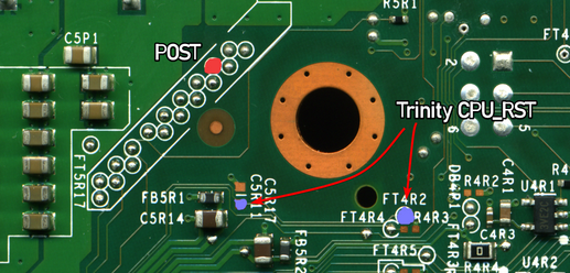
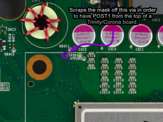
=====POST & RST===== | |||
*Bottom | |||
**[[File:TrinityPOSTandRST.png|frameless|517x517px]] | |||
**There are two RST points, either can be used. | |||
*Top (without postfix adapter, requires scraping) | |||
**[[File:CoronaTrinityPOST.png|523x523px]] | |||
*Top (with postfix Adapter) | |||
**[[File:PostfixadapterV1 example.gif|frameless|524x524px]] | |||
**A Postfix adapter can be used on Trinity in case the POST point is damaged. | |||
**The post pad you use on the adapter does not matter, as they connect to the same spot on the CPU anyway. It was only used for tuning the boot times of early I2C RGH methods. | |||
=====STBY_CLK===== | |||
*C3B10 (Top) | |||
**[[File:TrinityHanaCLK.jpg|frameless|516x516px]] | |||
*FT3N2 (Bottom) | |||
**[[File:Ft3n2.jpg|frameless|512x512px]] | |||
=====SMC===== | |||
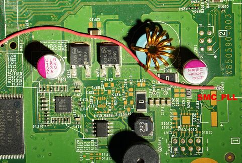
*The GPIO used for SMC_PLL is also used for Muffin/Mufas | |||
*SMC_PLL | |||
**Bottom | |||
***[[File:FT2V1.png|FT2V1|485x485px]] | |||
**Bottom (Alt point, requires scraping) | |||
***[[File:Trinity GPIO.png|483x483px]] | |||
** Top (Alt point; preferred for Muffin/Mufas) | |||
***[[File:Trinity smcpll.jpg|frameless|482x482px]] | |||
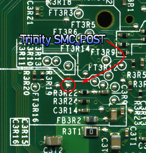
*SMC_POST | |||
** Bottom | |||
***[[File:TrinitySMC_POST.png|R3R22]] | |||
====Corona/Waitsburg/Stingray ==== | |||
=====3.3v, 5v, GND, and RGH 2 i2C===== | |||
* J2C3 | |||
**[[File:J2C3Corona.png|frameless|418x418px]] | |||
=====CPU_CLK '''(Only if using an X360 ACE V4/V5)'''===== | |||
*Top | |||
**[[File:CoronaCPUCLK.png|frameless|417x417px]] | |||
** There are two points circled for C1 and C2 respectively, either can be used or bridged. | |||
===== PLL===== | |||
*Bottom | |||
**[[File:RGH1.2 Slim PLL.jpg|frameless|391x391px]] | |||
**No alternative point! | |||
=====POST & RST===== | |||
*Bottom | |||
**[[File:Corona POSTandRST.png|frameless|392x392px]] | |||
**There are two RST points; either can be used. | |||
*Top (without postfix adapter) | |||
** [[File:CoronaTrinityPOST.png|394x394px]] | |||
*Top (Postfix Adapter) | |||
**[[File:PostfixadapterV1 example.gif|frameless|396x396px]] | |||
**If POST on the bottom is disabled (like in Waitsburg & Stingray boards) or damaged, a postfix adapter is required. | |||
** The post pad you use on the adapter does not matter, as they connect to the same spot on the CPU anyway. It was only used for tuning the boot times of early I2C RGH methods. | |||
==== Glitch Chip Pinouts ==== | |||
'''Note: RGH 1.2 on Corona consoles requires a glich chip with a built in oscillator.''' STBY_CLK will be unused when using a chip's oscillator. | '''Note: RGH 1.2 on Corona consoles requires a glich chip with a built in oscillator.''' STBY_CLK will be unused when using a chip's oscillator. | ||
==== Coolrunner Rev A/B/C/D ==== | ===== Coolrunner Rev A/B/C/D ===== | ||
*A - PLL (Phat) | |||
*B - STBY_CLK (only if not using oscillator on Phat or Trinity) | *B - STBY_CLK (only if not using oscillator on Phat or Trinity) | ||
**If you have a Rev D, the built in oscillator can be easily disabled if [[:File:Disable-enable-RevD-CLK.jpg|this resistor]] is removed instead of removing the entire oscillator. | ** If you have a Rev D, the built in oscillator can be easily disabled if [[:File:Disable-enable-RevD-CLK.jpg|this resistor]] is removed instead of removing the entire oscillator. | ||
*C - POST | * C - POST | ||
*D - RST | *D - RST | ||
* | *E - PLL (Slim, 5-10K ohm resistor recommended) | ||
==== CR3 Lite ==== | ===== CR3 Lite ===== | ||
*A - PLL ( | *A - PLL (Phat) | ||
*B - STBY_CLK (only if not using oscillator Phat or Trinity) | * B - STBY_CLK (only if not using oscillator Phat or Trinity) | ||
*C - POST | * C - POST | ||
*D - RST | *D - RST | ||
*E - PLL (Slim, 5-10K ohm resistor recommended) | |||
==== Matrix Glitcher ==== | ===== Matrix Glitcher ===== | ||
*A - RST | *A - RST | ||
*B - POST | *B - POST | ||
*C - STBY_CLK (only if not using oscillator Phat or Trinity) | *C - STBY_CLK (only if not using oscillator Phat or Trinity) | ||
**If you have a Matrix that comes with an oscillator, it can be easily disabled if [[:File:Matrix Glitcher's 0ohm Resistor for the Oscillator.jpeg|this resistor]] is removed instead of removing the entire oscillator. | **If you have a Matrix that comes with an oscillator, it can be easily disabled if [[:File:Matrix Glitcher's 0ohm Resistor for the Oscillator.jpeg|this resistor]] is removed instead of removing the entire oscillator. | ||
* | *E - PLL (Slim, 5-10K ohm resistor recommended) | ||
*F - PLL (Phat) | |||
==== Squirt ==== | ===== Squirt ===== | ||
*(Phat) Squirt BGA 1.2: Disable the onboard 670pf and/or 480pf caps by removing R7 and R8 | *(Phat) Squirt BGA 1.2: Disable the onboard 670pf and/or 480pf caps by removing R7 and R8 | ||
*(Phat) Squirt Reloaded 2.X: remove R2 and connect STBY_CLK | *(Phat) Squirt Reloaded 2.X: remove R2 and connect STBY_CLK | ||
| Line 94: | Line 226: | ||
[[File:1v8-X360ACE.jpg|thumb|1.8v on an Ace V3]] | [[File:1v8-X360ACE.jpg|thumb|1.8v on an Ace V3]] | ||
==== X360ACE (V1/V2/V3/V3+), DGX ==== | ===== X360ACE (V1/V2/V3/V3+), DGX ===== | ||
* C - POST | *C - POST | ||
* D - RST | *D - RST | ||
* E - STBY_CLK (Only when using 48 MHz timings on Phat) | *E - STBY_CLK (Only when using 48 MHz timings on Phat) | ||
* F - PLL (5-10K ohm resistor recommended on Slim, 22K ohm resistor required on Phat) | *F - PLL (5-10K ohm resistor recommended on Slim, 22K ohm resistor required on Phat) | ||
*Remember to remove the diode and connect 1.8V on Phat | *Remember to remove the diode and connect 1.8V on Phat | ||
==== X360ACE V4/V5 ==== | ===== X360ACE V4/V5 '''(Slim Only)''' ===== | ||
*A - RST | *A - RST | ||
* B - POST | *B - POST | ||
*C1 - CPU_CLK_DP | *C1 - CPU_CLK_DP | ||
*C2 - CPU_CLK_DN | *C2 - CPU_CLK_DN | ||
*D - PLL (5-10K ohm resistor recommended | *D - PLL (5-10K ohm resistor recommended) | ||
=== Glitch Chip Diagrams === | === Glitch Chip Diagrams === | ||
====Phat==== | ====== Phat Diagram for CR3 Lite ====== | ||
[[ | [[File:Cr3litergh12.jpg|frameless|400x400px]] | ||
[[ | ====== Phat Diagram for Coolrunner ====== | ||
[[File:Coolrunnerrevcrgh12.jpg|400x400px]] | |||
[[ | ====== Phat Diagram for Matrix ====== | ||
[[File:Matrixglitcherrgh12diagram.jpg|frameless|400x400px]] | |||
[[ | ====== Trinity Diagram for Matrix ====== | ||
[[File:RGH1.2 Trinity Diagram.jpg|frameless|536x536px]] | |||
[[ | ====== Corona Diagram for Matrix ====== | ||
[[File:RGH1.2 Corona Diagram.jpg|frameless|536x536px]] | |||
==== | ====== Phat Diagram for X360ACE ====== | ||
[[ | [[File:X360acergh12phatinstalldiagram.png|frameless|400x400px]] | ||
[[ | ====== Phat Diagram for Squirt ====== | ||
[[File:Squirtrgh12installdiagram.jpg|frameless|400x400px]] | |||
== Testing the Console == | == Testing the Console== | ||
Once you've finished soldering, clean up any flux with isopropyl alcohol and cotton swabs. Partially re-assemble your Xbox 360, ensuring that: | Once you've finished soldering, clean up any flux with isopropyl alcohol and cotton swabs. Partially re-assemble your Xbox 360, ensuring that: | ||
* Heatsinks are attached (If they were removed for some reason) | *Heatsinks are attached (If they were removed for some reason) | ||
* Fan(s) are in place and plugged in (On a phat console, the fans can be angled on top of the heatsinks to cool them for testing) | * Fan(s) are in place and plugged in (On a phat console, the fans can be angled on top of the heatsinks to cool them for testing) | ||
* The RF board is plugged into the front of the console | *The RF board is plugged into the front of the console | ||
* An A/V or HDMI cable is plugged into the Xbox 360 and into a TV or monitor | *An A/V or HDMI cable is plugged into the Xbox 360 and into a TV or monitor | ||
* A power brick is plugged in to both the wall and Xbox 360 | *A power brick is plugged in to both the wall and Xbox 360 | ||
* (Optional) An ethernet cable is plugged into the Xbox 360 and a LAN (e.g. a switch, router, or directly to a PC) | *(Optional) An ethernet cable is plugged into the Xbox 360 and a LAN (e.g. a switch, router, or directly to a PC) | ||
Turn on your console, and it should boot into XeLL RELOADED within a minute. If you don't have an ethernet cable connected, write down (and/or take a picture of) the "CPU Key" listed on screen. If the console doesn't boot into XeLL, check all previous steps and double check your wiring accuracy and quality. | Turn on your console, and it should boot into XeLL RELOADED within a minute. If you don't have an ethernet cable connected, write down (and/or take a picture of) the "CPU Key" listed on screen. If the console doesn't boot into XeLL, check all previous steps and double check your wiring accuracy and quality. | ||
==Decrypting the NAND== | ==Decrypting the NAND == | ||
Once you have successfully obtained your CPU key, we can build an XeBuild image, which is a modified NAND built specifically for your console. | Once you have successfully obtained your CPU key, we can build an XeBuild image, which is a modified NAND built specifically for your console. | ||
* If you want to use J-Runner with the console connected to LAN to get the CPU key, enter the IP address XeLL gives you into the lower right of the app. You can then click <code>Get CPU Key</code> and XeLL will automatically decrypt the retail NAND dump you backed up earlier. | * If you want to use J-Runner with the console connected to LAN to get the CPU key, enter the IP address XeLL gives you into the lower right of the app. You can then click <code>Get CPU Key</code> and XeLL will automatically decrypt the retail NAND dump you backed up earlier. | ||
* If you want to use XeLL's web page to get the CPU key, enter the Xbox's IP address in your preferred web browser. You will see information about the console, and the CPU key can be easily copy and pasted from this web page. | *If you want to use XeLL's web page to get the CPU key, enter the Xbox's IP address in your preferred web browser. You will see information about the console, and the CPU key can be easily copy and pasted from this web page. | ||
* If you didn't have access to an ethernet cable to plug the Xbox into a PC or LAN, you can manually type the CPU key into J-Runner in order to decrypt your original NAND dump. | * If you didn't have access to an ethernet cable to plug the Xbox into a PC or LAN, you can manually type the CPU key into J-Runner in order to decrypt your original NAND dump. | ||
== Writing New NAND Image (NAND Flasher) == | ==Writing New NAND Image (NAND Flasher) == | ||
#Power down the console, and connect your programmer to the motherboard. | #Power down the console, and connect your programmer to the motherboard. | ||
#*If you are using an xFlasher, ensure the switch is set to <code>SPI</code>. | #* If you are using an xFlasher, ensure the switch is set to <code>SPI</code>. | ||
#Open J-Runner and select <code>...</code> next to the Load Source field and select one of your original NAND dumps if not already selected. In the upper right of J-Runner, ensure the <code>Glitch2</code> radio button is selected. | #Open J-Runner and select <code>...</code> next to the Load Source field and select one of your original NAND dumps if not already selected. In the upper right of J-Runner, ensure the <code>Glitch2</code> radio button is selected. | ||
#Click "Create XeBuild Image". This will take a few moments. | # Click "Create XeBuild Image". This will take a few moments. | ||
# Click "Write NAND". | #Click "Write NAND". | ||
# Disconnect your NAND programmer from the console's motherboard when the process completes. | # Disconnect your NAND programmer from the console's motherboard when the process completes. | ||
# Check if the console boots to the Microsoft dashboard. If it successfully boots to the dashboard, it is an indication that you've successfully hacked your console. | #Check if the console boots to the Microsoft dashboard. If it successfully boots to the dashboard, it is an indication that you've successfully hacked your console. | ||
#Boot the console several times and ensure it boots consistently. If not, make sure your wiring is clean and neat and avoids noisy areas. Run the wires near the X-Clamps for best results. | #Boot the console several times and ensure it boots consistently. If not, make sure your wiring is clean and neat and avoids noisy areas. Run the wires near the X-Clamps for best results. | ||
#[[Xbox 360:RGH/RGH1.2#Tuning%20Boot%20Times|Tune boot times]] if necessary. | #[[Xbox 360:RGH/RGH1.2#Tuning%20Boot%20Times|Tune boot times]] if necessary. | ||
| Line 162: | Line 298: | ||
#Copy updflash.bin to a FAT32 formatted USB storage device and plug it into your powered-off console. | #Copy updflash.bin to a FAT32 formatted USB storage device and plug it into your powered-off console. | ||
#Turn on your console. It will boot into XeLL and begin flashing your NAND. Once it has finished, it will power off your console. | #Turn on your console. It will boot into XeLL and begin flashing your NAND. Once it has finished, it will power off your console. | ||
# Turn it back on, and it should boot to the Microsoft dashboard, which is an indication that you've successfully hacked your console. | #Turn it back on, and it should boot to the Microsoft dashboard, which is an indication that you've successfully hacked your console. | ||
#Boot the console several times and ensure it boots consistently. If not, make sure your wiring is clean and neat and avoids noisy areas. Run the wires near the X-Clamps for best results. | #Boot the console several times and ensure it boots consistently. If not, make sure your wiring is clean and neat and avoids noisy areas. Run the wires near the X-Clamps for best results. | ||
#[[Xbox 360:RGH/RGH1.2#Tuning%20Boot%20Times|Tune boot times]] if necessary. | #[[Xbox 360:RGH/RGH1.2#Tuning%20Boot%20Times|Tune boot times]] if necessary. | ||
#Continue in the [[Xbox 360:RGH/RGH1.2#Cleaning Up|Cleaning Up section]]. | #Continue in the [[Xbox 360:RGH/RGH1.2#Cleaning Up|Cleaning Up section]]. | ||
== Tuning Boot Times == | ==Tuning Boot Times== | ||
=== Jasper Consoles === | ===Jasper Consoles=== | ||
* If the console does not glitch reliably even after tuning the value, add a 68nf-100nf capacitor (ex: 683 cap or SMD cap) from PLL to GND. | *If the console does not glitch reliably even after tuning the value, add a 68nf-100nf capacitor (ex: 683 cap or SMD cap) from PLL to GND. | ||
* Onboard 100nf on Coolrunner Rev-C may be used by bridging CAP. | *Onboard 100nf on Coolrunner Rev-C may be used by bridging CAP. | ||
* Onboard 100nf on Squirt Reloaded 2.X may be used by bridging J5. | *Onboard 100nf on Squirt Reloaded 2.X may be used by bridging J5. | ||
* If adding a cap, PLL will be more sensitive to noise. If you have strange blinking, be sure that your wire is routed away from clock signals. | *If adding a cap, PLL will be more sensitive to noise. If you have strange blinking, be sure that your wire is routed away from clock signals. | ||
* For X360ACE/DGX make sure the capacitor is after the 22K Ohm resistor. | *For X360ACE/DGX make sure the capacitor is after the 22K Ohm resistor. | ||
=== Tuning Glitch Chip Timings (Phat) === | ===Tuning Glitch Chip Timings (Phat)=== | ||
Start at the top of the recommended range (noted in J-Runner's timing assistant and commented in the extra timings folders) and work down until you get good boots. On chips with crystals, the optimal timing will depend on the crystal (how close it is to its rated frequency) | Start at the top of the recommended range (noted in J-Runner's timing assistant and commented in the extra timings folders) and work down until you get good boots. On chips with crystals, the optimal timing will depend on the crystal (how close it is to its rated frequency) | ||
* If the light stays on at the end of a cycle: | *If the light stays on at the end of a cycle: | ||
** This means that the checks were passed, but the console failed to start | **This means that the checks were passed, but the console failed to start | ||
** The timing is probably too low, or the pulse length is too large | **The timing is probably too low, or the pulse length is too large | ||
* If the light goes off at the end of a cycle but doesn't boot: | *If the light goes off at the end of a cycle but doesn't boot: | ||
** This means that the checks failed | **This means that the checks failed | ||
** the timing is too high, or the pulse length is too small | **the timing is too high, or the pulse length is too small | ||
Note: The debug light behavior may be slightly misleading due to using POST_OUT bit 0. | Note: The debug light behavior may be slightly misleading due to using POST_OUT bit 0. | ||
=== Tuning Glitch Chip Timings (Slim) === | ===Tuning Glitch Chip Timings (Slim)=== | ||
Start at the top of the recommended range (noted in J-Runner's timing assistant and commented in the extra timings folders) and work down until you get good boots | Start at the top of the recommended range (noted in J-Runner's timing assistant and commented in the extra timings folders) and work down until you get good boots | ||
On chips with crystals, the optimal timing will depend on the crystal (how close it is to its rated frequency) | On chips with crystals, the optimal timing will depend on the crystal (how close it is to its rated frequency) | ||
* 2 Short Blinks, then Short | *2 Short Blinks, then Short | ||
** .....##...##...................##............ | **.....##...##...................##............ | ||
** This means that the checks were passed, but the console failed to start | **This means that the checks were passed, but the console failed to start | ||
** The timing is probably too low | **The timing is probably too low | ||
* 2 Short Blinks, then Long | *2 Short Blinks, then Long | ||
** .....##...##...................############## | **.....##...##...................############## | ||
** If the light stays on at the end of a cycle: | **If the light stays on at the end of a cycle: | ||
*** This means that the checks failed | ***This means that the checks failed | ||
*** The timing is probably too high or far too low | ***The timing is probably too high or far too low | ||
==Cleaning Up== | ==Cleaning Up== | ||
Remove your NAND programmer wires and clean the points. Clean all flux off the board, allow it to dry, and test it once more before re-assembling. | Remove your NAND programmer wires and clean the points. Clean all flux off the board, allow it to dry, and test it once more before re-assembling. | ||
You may want to leave your Xbox 360 disassembled so that you can [[Xbox_360:Disabling the eFuse Burning Circuit|disable the eFuse-blowing circuit]] so you can't accidentally install official updates on your console. | You may want to leave your Xbox 360 disassembled so that you can [[Xbox_360:Disabling the eFuse Burning Circuit|disable the eFuse-blowing circuit]] so you can't accidentally install official updates on your console. | ||
== Installing XeXMenu== | ==Installing XeXMenu== | ||
#Plug a flash drive into your Xbox 360 and navigate to Console Settings > Storage. Select the flash drive and allow the console to format the flash drive. | #Plug a flash drive into your Xbox 360 and navigate to Console Settings > Storage. Select the flash drive and allow the console to format the flash drive. | ||
#Extract the <code>CODE9999</code> folder from [https://mega.nz/#!9AlUmDZK!oykniipcx80kvuRxLaqY8NtPMJYKHW1ZYpqYfcAZsLA XeXMenu 1.2 rar] to your Desktop. | #Extract the <code>CODE9999</code> folder from [https://mega.nz/#!9AlUmDZK!oykniipcx80kvuRxLaqY8NtPMJYKHW1ZYpqYfcAZsLA XeXMenu 1.2 rar] to your Desktop. | ||
Latest revision as of 16:58, 10 December 2024
| The steps on this page are considered risky for your console, as there is a chance you can brick it. Please have someone else mod your console if you are not experienced in soldering! |
RGH1.2 combines RGH1-like PLL slowdown with Glitch2 images to allow reliable glitching of Falcon/Jasper consoles with split CB (post 14699 kernel). RGH1.2 V2 ports this hack to Trinity/Corona consoles as well as fixing a few issues on Jaspers.
Equipment Needed
- A compatible glitch chip:
- Coolrunner Rev A/B/C/D
- CR3 Lite
- Matrix Glitcher
- Squirt BGA/Reloaded
- X360ACE V1/V2/V3
- X360ACE V3+/V4/V5 (Trinity/Corona only)
- DGX
- A PC running Windows Vista or later
- A soldering iron, solder, flux, and Isopropyl alcohol with cotton swabs
- A NAND and glitch chip programmer:
- A NAND Backup with XeLL written to the console
- J-Runner with Extras (Includes RGH1.2 V2 Matrix/Coolrunner Timings)
- RGH1.2 V2 Timing Files (X360ACE/Squirt chips only)
Reading your NAND
4 GB Corona/Waitsburg/Stingray
4 GB Xbox 360 S/E SKUs made after mid 2011 use an MMC NAND (Corona) or eMMC chip (Waitsburg/Stingray/Winchester) and require different tools to dump and flash the NAND compared to the 16/64/256/512 MB NAND chips. These 4 GB consoles require that you use an xFlasher 360, PicoFlasher, Element18592's 4GB USB tool, or an SD card tool. Consider the pros and cons below and choose the method that’s right for you.
A guide on how to dump and write to a 4 GB NAND can be found here.
| Device | Pros | Cons |
|---|---|---|
| xFlasher 360 |
|
|
| PicoFlasher |
|
|
| 4GB USB Tool |
|
|
| SD Card Tool (any brand) |
|
|
All Other NAND Types
There are a few different tools for reading your NAND chip: xFlasher 360, Nand-X, JR Programmer, Matrix USB NAND Flasher, PicoFlasher, various SD card tools, or a LPT cable. Consider the pros and cons below and choose the method that’s right for you. An LPT cable is not recommended as it's extremely slow, requires more work than other options, and cannot be used to program glitch chips.
A guide on how to dump and write to a standard NAND can be found here.
| Device | Pros | Cons |
|---|---|---|
| xFlasher 360 |
|
|
| PicoFlasher |
|
|
| JR Programmer |
|
|
| Nand-X |
|
|
| Matrix USB NAND Flasher |
|
|
| LPT Cable |
|
|
Programming the Glitch Chip
Standard Xilinx-based Glitch Chip
This includes common chips like the CoolRunner, Matrix V1/V3, X360ACE V1/V2/V3, etc.
- Plug the cable from your programmer into the chip programmer.
- If you are using an xFlasher, ensure the switch is set to
SPI. - CoolRunner: Slide switch to "PRG".
- If you are using an xFlasher, ensure the switch is set to
- Open J-Runner with Extras. Click "Program Timing File" in the upper left, select the RGH 1.2 tab, and the relevant radio button for RGH 1.2.
- You can use the timing assistant in the bottom left to auto select a safe timing for your motherboard revision.
- When complete, unplug the cable from the glitch chip.
- Coolrunner: Set the switch back to "NOR".
X360ACE V3+/V4/V5
xFlasher 360 or other Gowin compatible programmer is required in order to program these chips.
Programming Instructions
Corona Specific Instructions
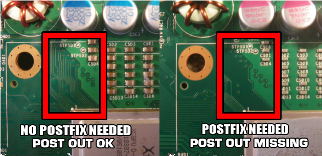
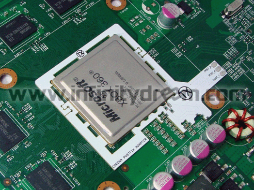
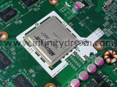
On later revisions of Corona based motherboards (named Waitsburg and Stingray for Xbox 360 S and E respectively), the trace connecting the CPU's POST to the POST pad on the bottom of the motherboard has been removed, so you need to use a postfix adapter to be able to attach a pogo pin to the POST connection underneath the CPU, allowing for CPU POST output once again. You can use the following image to determine if you need the adapter or not by removing the heatsink:
You can also identify if you have a Waitsburg motherboard instead of a Corona by looking for the part number of X862605 on the bottom left of the PCB. Generally, Xbox 360 S consoles manufactured in 2012 will be Waitsburgs and need postfix adapters for RGH. Every Stingray will also need a postfix adapter with RGH.
As shown in following diagram, you can install it by carefully sliding the larger piece of the adapter onto the left side of the CPU (when looking at the CPU from a readable position). Gently press the PCB inward toward the CPU to depress the pogo pin, and slide the smaller PCB part over the other side of the CPU, interlocking the two PCBs together. Solder the four anchor points on the edges of the postfix adapter to prevent it from coming loose.
Glitch Chip Installation
Motherboard Points
Phat
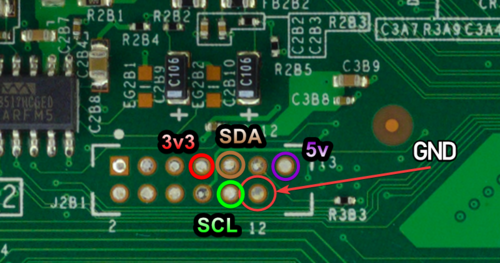
3.3v, 5v, and GND
1.8V (Only if using an X360 ACE V1/V2/V3)
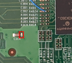
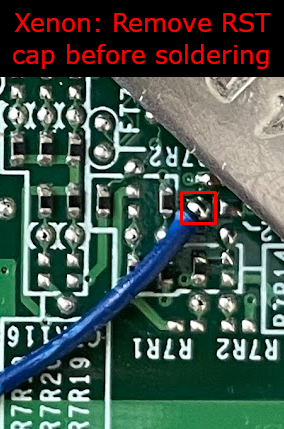
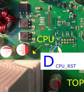
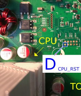
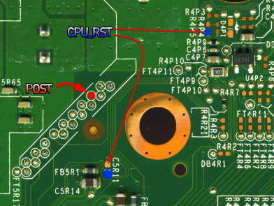
CPU_RST
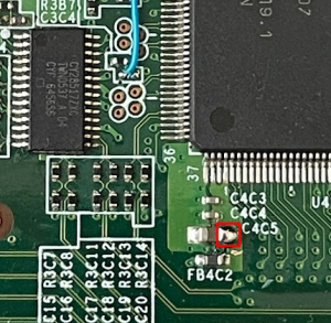
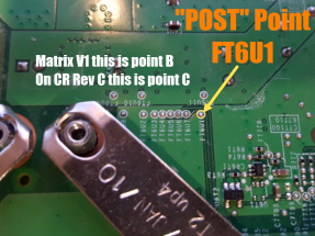
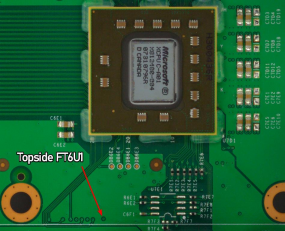
FT6U1 POST
GND
- J2B1 Header
- AV Port
- Any other ground point
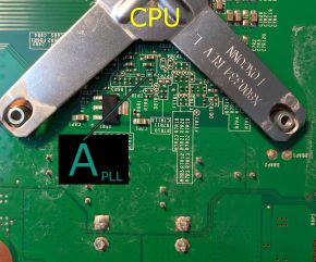
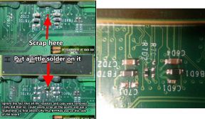
PLL
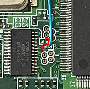
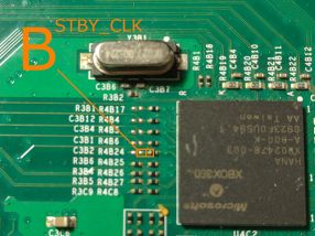
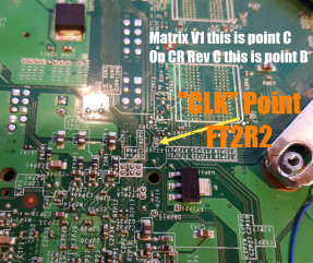
STBY_CLK
Trinity
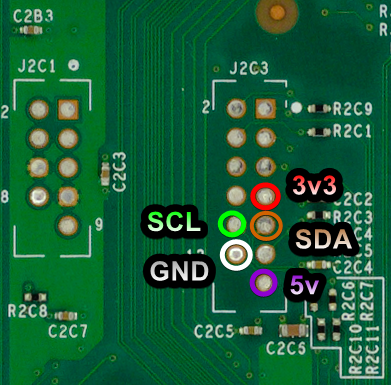
3.3v, 5v, and GND
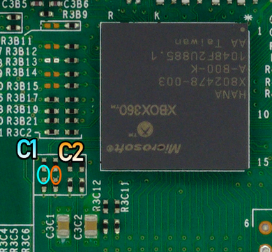
CPU_CLK (Only if using an X360 ACE V4/V5)
PLL
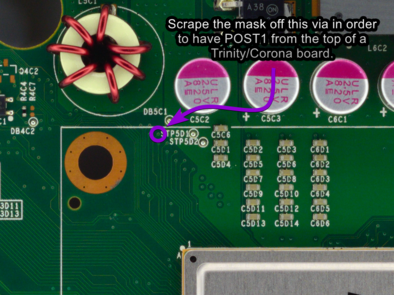
POST & RST
- Top (without postfix adapter, requires scraping)
- Top (with postfix Adapter)
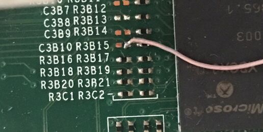
STBY_CLK
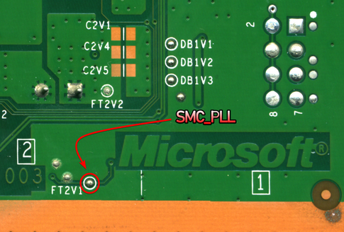
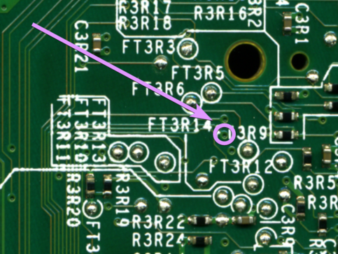
SMC
- The GPIO used for SMC_PLL is also used for Muffin/Mufas
- SMC_PLL
- SMC_POST
Corona/Waitsburg/Stingray
3.3v, 5v, GND, and RGH 2 i2C
CPU_CLK (Only if using an X360 ACE V4/V5)
PLL
POST & RST
- Bottom
- Top (without postfix adapter)
- Top (Postfix Adapter)
Glitch Chip Pinouts
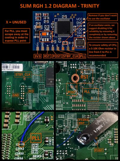
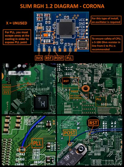
Note: RGH 1.2 on Corona consoles requires a glich chip with a built in oscillator. STBY_CLK will be unused when using a chip's oscillator.
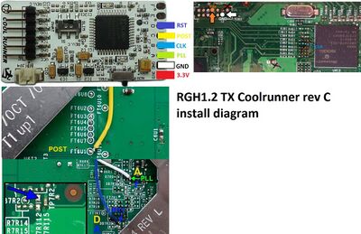
Coolrunner Rev A/B/C/D
- A - PLL (Phat)
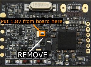
- B - STBY_CLK (only if not using oscillator on Phat or Trinity)
- If you have a Rev D, the built in oscillator can be easily disabled if this resistor is removed instead of removing the entire oscillator.
- C - POST
- D - RST
- E - PLL (Slim, 5-10K ohm resistor recommended)
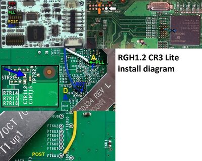
CR3 Lite
- A - PLL (Phat)
- B - STBY_CLK (only if not using oscillator Phat or Trinity)
- C - POST
- D - RST
- E - PLL (Slim, 5-10K ohm resistor recommended)
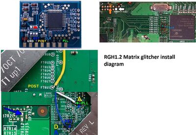
Matrix Glitcher
- A - RST
- B - POST
- C - STBY_CLK (only if not using oscillator Phat or Trinity)
- If you have a Matrix that comes with an oscillator, it can be easily disabled if this resistor is removed instead of removing the entire oscillator.
- E - PLL (Slim, 5-10K ohm resistor recommended)
- F - PLL (Phat)
Squirt
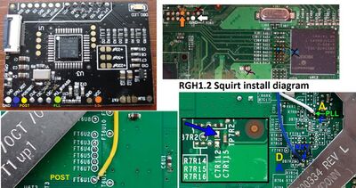
- (Phat) Squirt BGA 1.2: Disable the onboard 670pf and/or 480pf caps by removing R7 and R8
- (Phat) Squirt Reloaded 2.X: remove R2 and connect STBY_CLK
- (Slim) Squirt Reloaded 2.X: remove R2 and connect STBY_CLK or remove 100 MHz and add 48 MHz oscillator
- (Slim) Use SCL pad for PLL
- Pinout follows written labels
- Don't use POST or RST tuners
X360ACE (V1/V2/V3/V3+), DGX
- C - POST
- D - RST
- E - STBY_CLK (Only when using 48 MHz timings on Phat)
- F - PLL (5-10K ohm resistor recommended on Slim, 22K ohm resistor required on Phat)
- Remember to remove the diode and connect 1.8V on Phat
X360ACE V4/V5 (Slim Only)
- A - RST
- B - POST
- C1 - CPU_CLK_DP
- C2 - CPU_CLK_DN
- D - PLL (5-10K ohm resistor recommended)
Glitch Chip Diagrams
Phat Diagram for CR3 Lite
Phat Diagram for Coolrunner
Phat Diagram for Matrix
Trinity Diagram for Matrix
Corona Diagram for Matrix
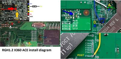
Phat Diagram for X360ACE
Phat Diagram for Squirt
Testing the Console
Once you've finished soldering, clean up any flux with isopropyl alcohol and cotton swabs. Partially re-assemble your Xbox 360, ensuring that:
- Heatsinks are attached (If they were removed for some reason)
- Fan(s) are in place and plugged in (On a phat console, the fans can be angled on top of the heatsinks to cool them for testing)
- The RF board is plugged into the front of the console
- An A/V or HDMI cable is plugged into the Xbox 360 and into a TV or monitor
- A power brick is plugged in to both the wall and Xbox 360
- (Optional) An ethernet cable is plugged into the Xbox 360 and a LAN (e.g. a switch, router, or directly to a PC)
Turn on your console, and it should boot into XeLL RELOADED within a minute. If you don't have an ethernet cable connected, write down (and/or take a picture of) the "CPU Key" listed on screen. If the console doesn't boot into XeLL, check all previous steps and double check your wiring accuracy and quality.
Decrypting the NAND
Once you have successfully obtained your CPU key, we can build an XeBuild image, which is a modified NAND built specifically for your console.
- If you want to use J-Runner with the console connected to LAN to get the CPU key, enter the IP address XeLL gives you into the lower right of the app. You can then click
Get CPU Keyand XeLL will automatically decrypt the retail NAND dump you backed up earlier. - If you want to use XeLL's web page to get the CPU key, enter the Xbox's IP address in your preferred web browser. You will see information about the console, and the CPU key can be easily copy and pasted from this web page.
- If you didn't have access to an ethernet cable to plug the Xbox into a PC or LAN, you can manually type the CPU key into J-Runner in order to decrypt your original NAND dump.
Writing New NAND Image (NAND Flasher)
- Power down the console, and connect your programmer to the motherboard.
- If you are using an xFlasher, ensure the switch is set to
SPI.
- If you are using an xFlasher, ensure the switch is set to
- Open J-Runner and select
...next to the Load Source field and select one of your original NAND dumps if not already selected. In the upper right of J-Runner, ensure theGlitch2radio button is selected. - Click "Create XeBuild Image". This will take a few moments.
- Click "Write NAND".
- Disconnect your NAND programmer from the console's motherboard when the process completes.
- Check if the console boots to the Microsoft dashboard. If it successfully boots to the dashboard, it is an indication that you've successfully hacked your console.
- Boot the console several times and ensure it boots consistently. If not, make sure your wiring is clean and neat and avoids noisy areas. Run the wires near the X-Clamps for best results.
- Tune boot times if necessary.
- Continue in the Cleaning Up section.
Writing a New NAND Image (XeLL)
| 4 GB Corona varients do not support currently support NAND flashing through XeLL. If XeLL is the only thing flashed to the NAND, it is required to use a NAND flasher. |
- Open J-Runner and select
...next to the Load Source field and select your nanddump1.bin or nanddump2.bin if not already selected. In the upper right corner of the window, select the dashboard version you chose for the patched dump that you wrote to the motherboard and make sure that theGlitch2radio button is selected. - Click "Create XeBuild Image". This will take a few moments.
- Copy updflash.bin to a FAT32 formatted USB storage device and plug it into your powered-off console.
- Turn on your console. It will boot into XeLL and begin flashing your NAND. Once it has finished, it will power off your console.
- Turn it back on, and it should boot to the Microsoft dashboard, which is an indication that you've successfully hacked your console.
- Boot the console several times and ensure it boots consistently. If not, make sure your wiring is clean and neat and avoids noisy areas. Run the wires near the X-Clamps for best results.
- Tune boot times if necessary.
- Continue in the Cleaning Up section.
Tuning Boot Times
Jasper Consoles
- If the console does not glitch reliably even after tuning the value, add a 68nf-100nf capacitor (ex: 683 cap or SMD cap) from PLL to GND.
- Onboard 100nf on Coolrunner Rev-C may be used by bridging CAP.
- Onboard 100nf on Squirt Reloaded 2.X may be used by bridging J5.
- If adding a cap, PLL will be more sensitive to noise. If you have strange blinking, be sure that your wire is routed away from clock signals.
- For X360ACE/DGX make sure the capacitor is after the 22K Ohm resistor.
Tuning Glitch Chip Timings (Phat)
Start at the top of the recommended range (noted in J-Runner's timing assistant and commented in the extra timings folders) and work down until you get good boots. On chips with crystals, the optimal timing will depend on the crystal (how close it is to its rated frequency)
- If the light stays on at the end of a cycle:
- This means that the checks were passed, but the console failed to start
- The timing is probably too low, or the pulse length is too large
- If the light goes off at the end of a cycle but doesn't boot:
- This means that the checks failed
- the timing is too high, or the pulse length is too small
Note: The debug light behavior may be slightly misleading due to using POST_OUT bit 0.
Tuning Glitch Chip Timings (Slim)
Start at the top of the recommended range (noted in J-Runner's timing assistant and commented in the extra timings folders) and work down until you get good boots
On chips with crystals, the optimal timing will depend on the crystal (how close it is to its rated frequency)
- 2 Short Blinks, then Short
- .....##...##...................##............
- This means that the checks were passed, but the console failed to start
- The timing is probably too low
- 2 Short Blinks, then Long
- .....##...##...................##############
- If the light stays on at the end of a cycle:
- This means that the checks failed
- The timing is probably too high or far too low
Cleaning Up
Remove your NAND programmer wires and clean the points. Clean all flux off the board, allow it to dry, and test it once more before re-assembling.
You may want to leave your Xbox 360 disassembled so that you can disable the eFuse-blowing circuit so you can't accidentally install official updates on your console.
Installing XeXMenu
- Plug a flash drive into your Xbox 360 and navigate to Console Settings > Storage. Select the flash drive and allow the console to format the flash drive.
- Extract the
CODE9999folder from XeXMenu 1.2 rar to your Desktop. - Plug the flash drive into your PC. Create a new folder on the flash drive and name it
0000000000000000(16 zeroes). Open the new folder, then drag theCODE9999folder into it. - Select Drive > Close, then close Xplorer360. Safely eject your flash drive and plug it into your Xbox 360. Navigate to the Demos section of your dashboard, and it should list XeXMenu there. Select it to launch it.
- You can install XeXMenu to your hard drive by going to Console Settings > Storage, and copying it from your flash drive to the hard drive.
From here, you can install any homebrew or mods that you want. See this page for a list of recommended modifications and applications to install.
